OMNICOMP GRAPHICS CORPORATION
TIGA FOR THE TEXAN ET
|
Category |
Video |
|
Video Types Supported |
XVGA |
|
Video Processor |
TMS34020 |
|
Highest Resolution Supported |
1600 x 1280 |
|
Data Bus Type |
16-bit ISA |
|
Memory Type |
DRAM/VRAM |
|
Maximum Onboard Memory |
8MB/4MB |
|
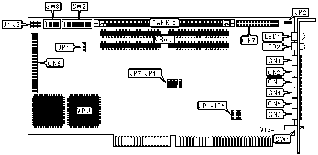
CONNECTIONS | |||
|
Purpose |
Location |
Purpose |
Location |
|
Red signal connector |
CN1 |
Vertical sync connector |
CN5 |
|
Green signal connector |
CN2 |
Frequency connector |
CN6 |
|
Blue signal connector |
CN3 |
VGA pass through connector |
CN7 |
|
Horizontal sync connector |
CN4 |
Serial port(s) daughter-board connector |
CN8 |
|
BASE I/O ADDRESS SELECTION | |||||||
|
Address |
SW2/1 |
SW2/2 |
SW2/3 |
SW2/4 |
SW2/5 |
SW2/6 | |
| » |
300h |
Off |
Off |
On |
On |
On |
On |
|
200h |
Off |
On |
On |
On |
On |
On | |
|
210h |
Off |
On |
On |
On |
On |
Off | |
|
220h |
Off |
On |
On |
On |
Off |
On | |
|
230h |
Off |
On |
On |
On |
Off |
Off | |
|
240h |
Off |
On |
On |
Off |
On |
Off | |
|
3B0h |
Off |
Off |
Off |
On |
Off |
Off | |
|
3C0h |
Off |
Off |
Off |
Off |
On |
On | |
|
3D0h |
Off |
Off |
Off |
Off |
On |
Off | |
|
3E0h |
Off |
Off |
Off |
Off |
Off |
On | |
|
3F0h |
Off |
Off |
Off |
Off |
Off |
Off | |
|
Note: A total of 32 base address settings are available. The jumpers are a binary representation of the decimal memory addresses. Switch SW2/1 is the Most Significant Bit and switch SW2/6 is the Least Significant Bit. The switches have the following decimal values: switch SW2/1=512, SW2/2=256, SW2/3=128,SW2/4=64, SW2/5=32, SW2/6=16. Turn off the switches and add the values of the switches that are off to obtain the correct memory address. (Off=1, On=0) | |||||||
|
VGA PASS THROUGH CONFIGURATION | ||
|
Setting |
SW2/7 | |
| » |
Enabled |
Off |
|
Disabled |
On | |
|
Note: If the VGA pass through connector is not connected to the board in the system, switch SW2/7 must be turned On. | ||
|
SYNC ON GREEN CONFIGURATION | |
|
Setting |
SW2/8 |
|
Disabled |
On |
|
Enabled |
Off |
|
SELF TEST & DEMONSTRATION CONFIGURATION | ||
|
Setting |
SW1 |
SW3/1 |
|
Enabled |
Press |
On |
|
Disabled |
Only press one time |
Off |
|
POWER UP RESOLUTION CONFIGURATION | |||
|
Setting |
SW3/2 |
SW3/3 |
SW3/4 |
|
640 x 512 color stereoscopic |
Off |
Off |
Off |
|
1024 x 960 interlaced Nucolor |
On |
Off |
Off |
|
1024 x 1024 mono stereoscopic |
Off |
On |
Off |
|
640 x 480 Nucolor |
On |
On |
Off |
|
1280 x 1024 60Hz |
Off |
Off |
On |
|
1600 x 1280 60Hz |
On |
Off |
On |
|
EEPROM |
On |
On |
On |
|
Note: Stereoscopic and Nucolor modes refer to the Tektronix Stereoscopic and NuColor monitors. | |||
|
DRAM MEMORY SELECTION | |||
|
Setting |
J3 |
JP1 | |
| » |
1MB or 2MB DRAM |
Open |
Pins 1 & 2 closed |
|
4MB or 8MB DRAM |
Closed |
Pins 2 & 3 closed | |
|
EEPROM PROGRAMMING CONFIGURATION | ||
|
Setting |
JP7 | |
| » |
+12V |
Pins 2 & 3 closed |
|
+5V |
Pins 1 & 2 closed | |
|
EEPROM POWER UP CONFIGURATION | ||
|
Setting |
JP8 | |
| » |
Write protected |
Pins 1 & 2 closed |
|
Not write protected |
Pins 2 & 3 closed | |
|
1 & 2 MBIT EEPROM DEVICES CONFIGURATION | ||
|
Setting |
JP10 | |
| » |
Enabled |
Pins 1 & 2 closed |
|
Disabled |
Pins 2 & 3 closed | |
|
BUS TYPE SELECTION | ||
|
Type |
J1 | |
| » |
16-bit |
Closed |
|
8-bit |
Open | |
|
VPU CONFIGURATION | ||
|
Setting |
JP2 | |
| » |
TMS34020 not halted |
Open |
|
TMS34020 halted |
Closed | |
|
INTERRUPT SELECTION | ||||
|
IRQ |
JP3 |
JP4 |
JP5 | |
| » |
Disabled |
Open |
Open |
Open |
|
2/9 |
Pins 2 & 3 closed |
Open |
Open | |
|
5 |
Pins 1 & 2 closed |
Open |
Open | |
|
10 |
Open |
Pins 2 & 3 closed |
Open | |
|
11 |
Open |
Pins 1 & 2 closed |
Open | |
|
14 |
Open |
Open |
Pins 2 & 3 closed | |
|
15 |
Open |
Open |
Pins 1 & 2 closed | |
|
DRAM CONFIGURATION | |
|
Size |
Bank 0 |
|
1MB |
(1) 256K x 36 |
|
2MB |
(1) 512K x 36 |
|
4MB |
(1) 1M x 36 |
|
8MB |
(1) 2M x 36 |
|
VRAM CONFIGURATION |
|
Note: 2MB of the 4MB of VRAM on board is located on the back of the board. |
|
FACTORY CONFIGURED - DO NOT ALTER | |
|
Jumper |
Position |
|
J2 |
Open |
|
JP9 |
Open |
|
DIAGNOSTIC LED(S) | ||||
|
LED1 Color |
LED1 Status |
LED2 Color |
LED2 Status |
Condition |
|
Green |
On |
Red |
On |
DRAM or serial port test initiated |
|
Green |
On |
Red |
Off |
VRAM test initiated |
|
Green |
Off |
Red |
Off |
RAMDAC or FPU test initiated |
|
Green |
Off |
Red |
On |
GSP test initiated |
|
Green |
Blinking |
Red |
Off |
Test has passed |
|
Green |
Off |
Red |
Blinking |
Test has failed |