RACAL-DATACOM
VA-2450P, VA-2450S, VA-2450G, VA-2450K, VA-2455P, VA-2455S, VA-2455G, VA-2455K
|
Card Type |
Modem (asynchronous) |
|
Chip Set |
Unidentified |
|
Maximum Data Rate |
2400bps |
|
Data Bus |
External |
|
Data Modulation Protocol |
Unidentified |
|
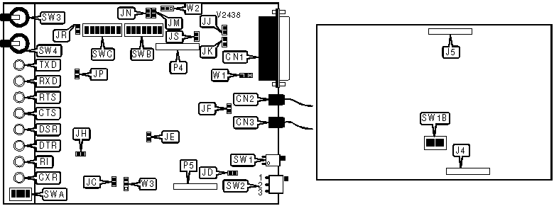
CONNECTIONS | ||||||
|
Function |
Label |
Function |
Label | |||
|
RS-232/422 |
CN1 |
Daughterboard header |
P4 | |||
|
DC power |
CN2 |
Daughterboard header |
P5 | |||
|
Line out |
CN3 |
Answer mode switch |
SW3 | |||
|
Header to main modem board |
J4 |
Loopback test switch |
SW4 | |||
|
Header to main modem board |
J5 | |||||
Note: Daughterboard included on VA-2455 models only. | ||||||
|
USER CONFIGURABLE SETTINGS | ||
|
Setting |
Label |
Position |
|
Carrier receive level set at 0dBm to -35dBm (switched-line) |
SWA/1 |
On |
|
Carrier receive level set at -10dBm to -45dBm (leased-line) |
SWA/1 |
Off |
|
í Phase equalization disabled |
SWA/2 |
Off |
|
Phase equalization enabled |
SWA/2 |
On |
|
í Factory configured - do not alter |
SWA/3 |
N/A |
|
í Factory configured - do not alter |
SWA/4 |
N/A |
|
í Factory configured - do not alter |
SWB/1 |
N/A |
|
í New synchronization pulse generation disabled |
SWB/2 |
Off |
|
New synchronization pulse generation enabled |
SWB/2 |
On |
|
í Modem uses internal clock source |
SWB/3 |
On |
|
Modem uses external clock source |
SWB/3 |
Off |
|
DTR normal |
SWB/4 |
Off |
|
DTR forced high |
SWB/4 |
On |
|
USER CONFIGURABLE SETTINGS (CON’T) | ||
|
Setting |
Label |
Position |
|
í Transmit clock separated from receive clock |
SWB/5 |
Off |
|
Receive clock looped through to transmit clock |
SWB/5 |
On |
|
í DSR forced low when modem is in test mode |
SWB/6 |
Off |
|
DSR normal when modem is in test mode |
SWB/6 |
On |
|
í RTS normal |
SWB/7 |
Off |
|
RTS forced high |
SWB/7 |
On |
|
í 50ms delay from carrier signal to raise DCD |
SWC/1 |
On |
|
10ms delay from carrier signal to raise DCD |
SWC/1 |
Off |
|
í 275ms delay from answer tone to RTS disabled |
SWC/2 |
Off |
|
275ms delay from answer tone to RTS enabled |
SWC/2 |
On |
|
í 160ms delay from CTS to RTS |
SWC/3 |
On |
|
7.1ms delay from CTS to RTS |
SWC/3 |
Off |
|
í Local echo disabled |
SWC/4 |
Off |
|
Local echo enabled |
SWC/4 |
On |
|
í 105ms transmit to receive delay enabled |
SWC/5 |
On |
|
105ms transmit to receive delay disabled |
SWC/5 |
Off |
|
í Factory configured - do not alter |
SWC/6 |
N/A |
|
í Modem will pick up the line only when handset is off-hook |
SWC/7 |
Off |
|
Modem will pick up the line only when handset is on-hook |
SWC/7 |
On |
|
í Factory configured - do not alter |
JA |
N/A |
|
í Factory configured - do not alter |
JB |
N/A |
|
Modem will disconnect on reversal of line current |
JD |
Open |
|
Modem will not disconnect on reversal of line current |
JD |
Closed |
|
í Factory configured - do not alter |
JE |
Open |
|
í Signal ground not connected to chassis ground |
JF |
Open |
|
Signal ground connected to chassis ground |
JF |
Closed |
|
í Factory configured - do not alter |
JG |
N/A |
|
í Factory configured - do not alter |
JH |
Open |
|
í Factory configured - do not alter |
JI |
N/A |
|
í Analog loopback and busy out controls on pins 18 and 25 disabled |
JJ |
Closed |
|
Analog loopback and busy out controls on pins 18 and 25 enabled |
JJ |
Open |
|
í Pin 18 or 25 controls busy out only |
JK |
Open |
|
Pin 18 or 25 controls analog loopback test and busy out |
JK |
Closed |
|
í Factory configured - do not alter |
JL |
N/A |
|
í Receive clock follows transmit clock when no carrier signal is present |
JM |
Open |
|
Receive clock forced high when no carrier signal is present |
JM |
Closed |
|
í SW3 functions enabled |
JP |
Closed |
|
SW3 functions disabled |
JP |
Open |
|
í Factory configured - do not alter |
JO |
N/A |
|
í Factory configured - do not alter |
JQ |
N/A |
|
USER CONFIGURABLE SETTINGS (CON’T) | ||
|
Setting |
Label |
Position |
|
í CTS normal |
JR |
Open |
|
CTS follows RTS |
JR |
Closed |
|
í Auto-answer enabled |
JS |
Open |
|
Auto-answer disabled |
JS |
Closed |
|
Signal receive level set at switched-line levels |
SW1B/1 |
On |
|
Signal receive level set at leased-line levels |
SW1B/1 |
Off |
|
í Secondary channel transmission attenuation set to -5dBm |
SW1B/2 |
Off |
|
Secondary channel transmission attenuation set to 0dBm |
SW1B/2 |
On |
|
í Secondary channel local echo disabled |
SW1B/3 |
On |
|
Secondary channel local echo enabled |
SW1B/3 |
Off |
|
í Secondary channel data rate set to 150bps |
SW1B/4 |
On |
|
Secondary channel data rate set to 75bps |
SW1B/4 |
Off |
|
í Analog loopback test and/or busy out controlled by pin 25 |
W1 |
Pins 2 & 3 closed |
|
Analog loopback test and/or busy out controlled by pin 18 |
W1 |
Pins 1 & 2 closed |
|
Hardware configuration is used |
W2 |
Pins 2 & 3 closed |
|
Factory configuration is used |
W2 |
Pins 1 & 2 closed |
|
LINE TYPE | ||
|
Setting |
JC |
JN |
|
Switched line |
Closed |
Open |
|
2-wire leased line |
Closed |
Closed |
|
4-wire leased line |
Open |
Closed |
|
TRANSMISSION LEVEL | |
|
Setting |
W3 |
|
Permissive (-10dBm) |
Pins 1 & 2 closed |
|
Leased-line (0dBm) |
Pins 2 & 3 closed |
|
Programmable |
Open |
|
DIAGNOSTIC LED(S) | |||
|
LED |
Color |
Status |
Condition |
|
TXD |
Red |
On |
Modem is transmitting data |
|
TXD |
Red |
Off |
Modem is not transmitting data |
|
RXD |
Red |
On |
Modem is receiving data |
|
RXD |
Red |
Off |
Modem is not receiving data |
|
RTS |
Red |
On |
RTS signal is high |
|
RTS |
Red |
Off |
RTS signal is low |
|
CTS |
Red |
On |
CTS signal is high |
|
CTS |
Red |
Off |
CTS signal is low |
|
DSR |
Red |
On |
DSR signal is high |
|
DSR |
Red |
Off |
DSR signal is low |
|
DTR |
Red |
On |
DTR signal is high |
|
DTR |
Red |
Off |
DTR signal is low |
|
RI |
Red |
Blinking |
Phone is ringing |
|
RI |
Red |
Off |
Phone is not ringing |
|
CXR |
Red |
On |
Carrier signal detected |
|
CXR |
Red |
Off |
Carrier signal not detected |
|
MISCELLANEOUS TECHNICAL NOTES |
|
The -S and -P models are permissive and programmable switched line modems, respectively. The -G and -K models are 2-wire and 4-wire leased line modems, respectively. The defaults for the jumpers reflect these differences where applicable. |