MAXTECH CORPORATION
MAXTECH V.32BIS EXTERNAL
|
Card Type |
Modem(synchronous/asynchronous) |
|
Chip Set |
Unidentified |
|
Maximum Data Rate |
14.4Kbps |
|
Maximum Fax Rate |
14.4Kbps |
|
Data Bus |
External |
|
Fax Class |
Class I & II |
|
Data Modulation Protocol |
Bell 103A/212A ITU-T V.21, V.22, V.22bis, V.32, V.32bis |
|
Fax Modulation Protocol |
ITU-T V.17, V.21CH2, V.27ter, V.29 |
|
Error Correction/Compression |
MNP5, V.42, V.42bis |
|
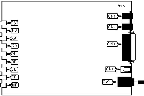
CONNECTIONS | ||||||
|
Function |
Label |
Function |
Label | |||
|
Line in |
CN1 |
DC power |
CN4 | |||
|
Line out |
CN2 |
Power switch |
SW1 | |||
|
RS-232/422 |
CN3 | |||||
|
DIAGNOSTIC LED(S) | |||
|
LED |
Color |
Status |
Condition |
|
TST |
Red |
On |
Normal operation |
|
TST |
Red |
Blinking |
Error detected and corrected |
|
HS |
Red |
On |
Modem is operating at 4800bps or faster |
|
HS |
Red |
Off |
Modem is operating at slower than 4800bps |
|
AA |
Red |
On |
Auto-answer enabled |
|
AA |
Red |
Off |
Auto-answer disabled |
|
AA |
Red |
Blinking |
Phone is ringing |
|
CD |
Red |
On |
Carrier signal detected |
|
CD |
Red |
Off |
Carrier signal not detected |
|
OH |
Red |
On |
Modem is off-hook |
|
OH |
Red |
Off |
Modem is on-hook |
|
RD |
Red |
On |
Modem is receiving data |
|
RD |
Red |
Off |
Modem is not receiving data |
|
SD |
Red |
On |
Modem is transmitting data |
|
SD |
Red |
Off |
Modem is not transmitting data |
|
TR |
Red |
On |
DTR signal is high |
|
TR |
Red |
Off |
DTR signal is low |
|
MR |
Red |
On |
Power is on |
|
MR |
Red |
Off |
Power is off |
Proprietary AT Command Set
|
ACCEPT RELIABLE MODE | |
|
Type: |
Immediate |
|
Format: |
AT [cmds] \Un |
|
Description: |
Accepts remote modem’s request for reliable link |
|
AUTO CONNECT | |
|
Type: |
Configuration |
|
Format: |
AT [cmds] %Pn [cmds] |
|
Description: |
Modem automatically dials number stored by &Z0 on power up |
|
Command |
Function |
|
%P0 |
Auto connect disabled |
|
%P1 |
Auto connect enabled |
|
AUTO-RETRAIN | |
|
Type: |
Configuration |
|
Format: |
AT %En |
|
Description: |
Selects auto-retrain mode. |
|
Command |
Function |
|
%E0 |
Auto-retrain disabled. |
|
í %E1 |
Auto-retrain enabled. |
|
AUTO-RELIABLE TIME BUFFER CONFIGURATION | ||
|
Type: |
Configuration | |
|
Format: |
AT [cmds] \Cn [cmds] | |
|
Description: |
Controls the handling of incoming data during auto-reliable time period. | |
|
Command |
Function | |
|
\CO |
Data is discarded | |
|
í \C1 |
Data is buffered | |
|
\C2 |
Data is discarded, sets to normal mode | |
|
AUTO-RELIABLE FALLBACK CHARACTER | |
|
Type: |
Configuration |
|
Format: |
AT [cmds] %An [cmds] |
|
Default: |
Unidentified |
|
Range: |
0-127 |
|
Unit: |
ASCII |
|
Description: |
Sets the character used as the auto-reliable fallback character |
|
BIT-MAPPED REGISTER S14 | ||
|
Format |
AT [cmds] S14=n [cmds] | |
|
Default: |
154 | |
|
Range: |
0 - 190 | |
|
Unit: |
Bit-mapped | |
|
Description: |
Controls command echo, result codes, dialing mode, and answer/originate mode | |
|
Bit |
Value |
Function |
|
0 |
0 |
Not used |
|
1 |
0 í 1 |
Command echo off Command echo on |
|
2 |
í 01 |
Result codes enabled Result codes disabled |
|
3 |
0 í 1 |
Numeric result codes Verbose result codes |
|
4 |
í 11 |
Dumb mode disabled Dumb mode enabled |
|
5 |
í 01 |
Tone dialing selected Pulse dialing selected |
|
6 |
0 |
Not used |
|
7 |
0 í 1 |
Answer mode selected Originate mode selected |
|
BIT-MAPPED REGISTER S21 | ||
|
Format |
AT [cmds] S21=n [cmds] | |
|
Default: |
Unidentified | |
|
Range: |
0 - 255 | |
|
Unit: |
Bit-mapped | |
|
Description: |
Selects originate only, switched/leased line, CTS signal, low DTR action, DCD signal, DSR signal, and long space disconnect | |
|
Bit |
Value |
Function |
|
0 |
í 01 |
Originate only disabled Originate only enabled |
|
1 |
0 1 |
Switched line Leased line |
|
2 |
0 1 |
CTS follows RTS CTS forced high |
|
4, 3 |
00 01 í 1011 |
DTR signal ignored Modem goes to command mode on low DTR Modem disconnects on low DTR. Auto-Answer is disabled Modem is initialized on low DTR |
|
5 |
0 í 1 |
DCD forced high DCD normal |
|
6 |
í 01 |
DSR forced high DSR normal |
|
7 |
í 01 |
Long Space Disconnect function disabled Long Space Disconnect function enabled |
|
BIT-MAPPED REGISTER S22 | ||
|
Format |
AT [cmds] S22=n [cmds] | |
|
Default: |
118 | |
|
Range: |
0 - 255 | |
|
Unit: |
Bit-mapped. | |
|
Description: |
Controls volume and speaker settings, result codes, and make/break pulse ratio | |
|
Bit |
Value |
Function |
|
1, 0 |
00 01 í 1011 |
Not used Low volume setting Medium volume setting Highest volume setting |
|
3, 2 |
00 í 0110 11 |
Speaker disabled Speaker enabled until carrier signal detected Speaker enabled Speaker off during dialing |
|
6, 5 ,4 |
000 001 010 011 100 101 110 í 111 |
Busy and dialtone detection disabled, result codes 0-4 enabled Not used Not used Not used Busy and dialtone detection disabled, result codes 0-5, 10 enabled Busy tone detection disabled, dialtone detection enabled, result codes 0-6, 10 enabled Busy tone detection enabled, dialtone detection disabled, result codes 0-5, 7, 10 enabled Busy and dialtone detection enabled, all result codes enabled |
|
7 |
í 01 |
39/61ms at 10pps (North America) 33/67ms at 10pps (Europe) |
|
BIT-MAPPED REGISTER S23 | ||
|
Format |
AT [cmds] S23=n [cmds] | |
|
Default: |
5 | |
|
Range: |
0-255 | |
|
Unit: |
Bit-mapped. | |
|
Description: |
Controls DTE rate and parity, and sets guard tone | |
|
Bit |
Value |
Function |
|
3, 2, 1, 0 |
0000 0001 0010 0011 0100 í 01010110 0111 1000 1001 1010 |
Sets serial port speed to 300bps Not used Sets serial port speed to 1200bps Sets serial port speed to 2400bps Sets serial port speed to 4800bps Sets serial port speed to 9600bps Sets serial port speed to 14.4Kbps Sets serial port speed to 19.2Kbps Sets serial port speed to 38.4Kbps Sets serial port speed to 57.6Kbps Sets serial port speed to 115.2Kbps |
|
5,4 |
í 0001 10 11 |
Parity even Space parity Parity odd Mark or no parity |
|
7, 6 |
00 01 10 |
550Hz guard tone enabled 1800Hz guard tone enabled Not used |
|
BIT-MAPPED REGISTER S27 | ||
|
Format |
AT [cmds] S27=n [cmds] | |
|
Default: |
Unidentified | |
|
Range: |
0-251 | |
|
Unit: |
Bit-mapped | |
|
Description: |
Selects sync/async mode, clock source and speed | |
|
Bit |
Value |
Function |
|
1, 0 |
00 01 í 1011 |
Asynchronous operation Synchronous connect mode Synchronous operation Synchronous on high DTR |
|
3, 2 |
00 01 10 11 |
Internal DTE transmit clock source External DTE transmit clock source Slave DTE transmit clock source Not used |
|
7, 6, 5, 4 |
0000 0001 0010 0011 0100 0101 0110 0111 1000 1001 1010 1011 1100 1101 1110 1111 |
Connect at 300bps Connect at 1200bps Connect at 2400bps Not used Connect at 4800bps Connect at 9600bps Not used Not used Not used Not used Not used Not used Connect at 7200bps Connect at 1200 bps Connect at 14.4Kbps Not used |
|
BIT-MAPPED REGISTER S28 | |||||
|
Format: |
AT [cmds] S28=n [cmds] | ||||
|
Default: |
16 | ||||
|
Range: |
147 | ||||
|
Description: |
Auto connect, callback, Bell/ITU-T protocol | ||||
|
Bit |
Value |
Function | |||
|
0 |
í 01 |
Power on auto connect disabled Power on auto connect enabled | |||
|
2, 1 |
í 0001 10 11 |
Callback disabled Callback enabled Password check enabled Not used | |||
|
3 |
0 |
Not used | |||
|
7, 6, 5, 4 |
0000 í 00010010 0011 0100 0101 0110 0111 1000 1001 1010 1011 1100 1101 1110 1111 |
ITU-T protocol Bell protocol Autoscan V.23 only Bell 103 only V.22/Bell 212A only V.22bis only V.32 4800bps only V.32 9600bps only V.32bis only Not used Not used Not used Not used Not used Not used | |||
|
BREAK TYPE | |||||
|
Type: |
Configuration | ||||
|
Format: |
AT [cmds] \Kn [cmds] | ||||
|
Description: |
Configures action of break signal. | ||||
|
Command |
Break from DTE while in reliable/normal mode |
Break from DTE while in direct mode |
Modem receives break from DTE while in command mode |
Break from remote modem while in normal mode | |
|
\K0 |
Do not send break to remote modem. |
Send break to remote modem immediately, then enter command mode. |
Buffers cleared and break sent to remote modem. |
Buffers cleared and break sent to DTE. | |
|
\K1 |
Buffers cleared and break sent to remote modem. |
Send break to remote modem immediately. |
Buffers cleared and break sent to remote modem. |
Buffers cleared and break sent to DTE. | |
|
\K2 |
Do not send break to remote modem. |
Send break to remote modem immediately, then enter command mode. |
Send break to remote modem immediately. |
Send break to DTE immediately. | |
|
\K3 |
Send break to remote modem immediately. |
Send break to remote modem immediately. |
Send break to remote modem immediately. |
Send break to DTE immediately. | |
|
\K4 |
Do not send break to remote modem. |
Send break to remote modem immediately, then enter command mode. |
Send break to remote modem with transmitted data. |
Break sent with received data to the DTE. | |
|
í \K5 |
Send break with transmitted data. |
Send break to remote modem immediately. |
Send break to remote modem with transmitted data. |
Break sent with received data to the DTE. | |
|
CLEAR DOWN | ||
|
Type: |
Configuration | |
|
Format: |
AT [cmds] %Dn [cmds] | |
|
Description: |
Sends clear down signal when terminating a connection | |
|
Command |
Function | |
|
%D0 |
Clear down disabled | |
|
í %D1 |
Clear down enabled | |
|
COMPRESSION | |
|
Type: |
Configuration |
|
Format: |
AT %Cn |
|
Description: |
Selects data compression |
|
Command |
Function |
|
%C0 |
V.42bis/MNP5 data compression disabled |
|
í %C1 |
V.42bis/MNP5 data compression enabled |
|
CONNECT MODE | |
|
Type: |
Configuration |
|
Format: |
AT [cmds] \Nn [cmds] |
|
Description: |
Sets connect mode. |
|
Command |
Function |
|
\N0 |
Normal mode enabled. |
|
\N1 |
Direct mode enabled. |
|
\N2 |
MNP mode only enabled. |
|
\N3 |
MNP or normal mode enabled. |
|
\N4 |
V.42 mode only enabled. |
|
\N5 |
V.42 or MNP enabled. |
|
í \N6 |
V.42, MNP and normal modes enabled. |
|
CONVERT TO RELIABLE MODE | |
|
Type: |
Configuration |
|
Format: |
AT [cmds] \Y [cmds] |
|
Description: |
Switch to reliable link from normal link |
|
ECHO DATA | |
|
Type: |
Configuration |
|
Format: |
AT [cmds] \En [cmds] |
|
\Example: |
AT \E0 <CR> |
|
Description: |
Enables modem to echo received data |
|
Command |
Function |
|
í \E0 |
Data echo disabled |
|
\E1 |
Data echo enabled |
|
EXTENDED RESULT CODES | |
|
Type: |
Configuration |
|
Format: |
AT [cmds] \Vn [cmds] |
|
Description: |
Enables transmission of result codes. |
|
Command |
Function |
|
\V0 |
Disable sending extended result codes and report DCE speed |
|
í \V1 |
Send extended result codes and report DCE speed |
|
\V2 |
Disable sending extended result codes and report DTE speed |
|
\V3 |
Send extended result codes and report DTE speed |
|
FLOW CONTROL | |
|
Type: |
Configuration |
|
Format: |
AT [cmds] \Gn [cmds] |
|
Description: |
Selects DCE flow control |
|
Command |
Function |
|
í \G0 |
DCE flow control disabled |
|
\G1 |
DCE flow control enabled |
|
FLOW CONTROL TYPE | |
|
Type: |
Configuration |
|
Format: |
AT [cmds] \Qn [cmds] |
|
Description: |
Sets type of flow control used by modem |
|
Command |
Function |
|
\Q0 |
Flow control disabled |
|
\Q1 |
Bidirectional XON/XOFF flow control enabled |
|
Í \Q2 |
CTS flow control by DCE enabled |
|
í \Q3 |
Bidirectional CTS/RTS flow control enabled |
|
\Q4 |
XON/XOFF flow control by DCE enabled |
|
INACTIVITY TIMER | |
|
Type: |
Configuration |
|
Format: |
AT [cmds] \Tn [cmds] |
|
Default: |
0 |
|
Range: |
0-90 |
|
Unit: |
1 minute |
|
Description: |
Sets the length of time that the modem does not receive information before it disconnects |
|
LOCK SERIAL PORT | |
|
Type: |
Configuration |
|
Format: |
AT [cmds] \Jn [cmds] |
|
Description: |
Sets operation of serial port speed. |
|
Command |
Function |
|
í \J0 |
Serial speed locked. |
|
\J1 |
Serial speed follows connect speed. |
|
MAXIMUM BLOCK SIZE FOR TRANSMISSION | |
|
Type: |
Configuration |
|
Format: |
AT [cmds] \An [cmds] |
|
Description: |
Sets the maximum transmittable block size. |
|
Command |
Function |
|
\A0 |
Maximum MNP block size is 64 characters. |
|
\A1 |
Maximum MNP block size is 128 characters. |
|
\A2 |
Maximum MNP block size is 192 characters. |
|
í \A3 |
Maximum MNP block size is 256 characters. |
|
ON-LINE IN RELIABLE MODE | |
|
Type: |
Configuration |
|
Format: |
AT [cmds] \O |
|
Description: |
Request reliable mode connection |
|
PASSWORD/CALLBACK | |
|
Type: |
Configuration |
|
Format: |
AT [cmds] %Sn [cmds] |
|
Description: |
Modem checks password, disconnects and calls stored number |
|
Command |
Function |
|
%S1 |
Request password |
|
%S2 |
Request password, request stored number location, disconnect, dial stored number |
|
PASSWORD SET | |
|
Type: |
Configuration |
|
Format: |
AT [cmds] \P=n [cmds] |
|
Unit: |
Up to 7 ASCII characters |
|
Description: |
Stores password. \P=? displays stored password. |
|
SWITCH TO NORMAL MODE | |
|
Type: |
Immediate |
|
Format: |
AT [cmds] \Z [cmds] |
|
Description: |
Empty buffers, switch from reliable to normal mode |
|
TEST STATUS | ||
|
Format: |
AT [cmds] S16=n [cmds] | |
|
Default: |
Read-only | |
|
Range: |
0 - 255 | |
|
Unit: |
Bit-mapped | |
|
Description: |
Contains status of loopback tests. | |
|
Bit |
Value |
Function |
|
0 |
0 í 1 |
Local analog loopback test not in progress. Local analog loopback test in progress. |
|
1 |
0 í 1 |
Clear down signal disabled Clear down signal enabled |
|
2 |
0 1 |
Local digital loopback test not in progress. Local digital loopback test in progress. |
|
3 |
0 |
Not used |
|
5, 4 |
00 01 10 11 |
Disable sending extended result codes and report DCE speed Send extended result codes and report DCE speed Disable sending extended result codes and report DTE speed Disable sending extended result codes and report DCE speed |
|
TRANSMIT LEVEL | |
|
Type: |
Configuration |
|
Format: |
AT [cmds] %Ln [cmds] |
|
Default: |
12 |
|
Range: |
0-15 |
|
Unit: |
-1 dBm |
|
Description: |
Selects transmit level |
|
XON/XOFF PASS-THROUGH | |
|
Type: |
Configuration |
|
Format: |
AT [cmds] \Xn [cmds] |
|
Description: |
Selects whether XON/XOFF signals are sent to remote modem |
|
Command |
Function |
|
í \X0 |
XON/XOFF signals trapped by local modem |
|
\X1 |
XON/XOFF passed through local modem |