MOTOROLA, INC.
V.3400
|
Modem Type |
Data (synchronous/asynchronous)/Fax |
|
Maximum Data Rate |
28.8Kbps |
|
Maximum Fax Rate |
14.4Kbps |
|
Data Bus |
External |
|
Fax Class |
Class I |
|
Data Modulation Protocol |
Bell 103A/212A ITU-T V.21, V.22, V.22bis, V.32, V.32bis, V.33, V.34 |
|
Fax Modulation Protocol |
ITU-T V.17, V.21CH2, V.27ter, V.29 |
|
Error Correction/Compression |
MNP5, V.42, V.42bis |
|
CONNECTIONS | |||
|
Purpose |
Location |
Purpose |
Location |
|
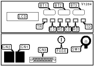
YES button |
BT1 |
Leased line out |
CN2 |
|
NO button |
BT2 |
RS-232/422 |
CN3 |
|
TALK/DATA button |
BT3 |
Fuse |
FUSE |
|
Switched line out |
CN1 |
Power switch |
SW1 |
|
DIAGNOSTIC LED(S) | |||
|
LED |
Color |
Status |
Condition |
|
TR |
Red |
On |
DTR signal is high |
|
TR |
Red |
Off |
DTR signal is low |
|
CS |
Red |
On |
CTS signal is high |
|
CS |
Red |
Off |
CTS signal is low |
|
RS |
Red |
On |
RTS signal is high |
|
RS |
Red |
Off |
RTS signal is low |
|
CD |
Red |
On |
Carrier signal detected |
|
CD |
Red |
Off |
Carrier signal not detected |
|
RD |
Red |
On |
Modem is receiving data |
|
RD |
Red |
Off |
Modem is not receiving data |
|
TD |
Red |
On |
Modem is transmitting data |
|
TD |
Red |
Off |
Modem is not transmitting data |
Proprietary AT Command Set
|
ANSWER/ORIGINATE MODE | |
|
Type: |
Configuration |
|
Format: |
AT [cmds] *ORn [cmds] |
|
Example: |
AT *OR0 <CR> |
|
Description: |
Selects whether the modem is in answer or originate mode. |
| Command |
Function |
| » *OR0 |
Modem is in originate mode. |
| *OR1 |
Modem is in answer mode. |
|
AUTO-ANSWER OVERRIDE | |
|
Type: |
Immediate |
|
Format: |
AT [cmds] *IC [cmds] |
|
Example: |
AT *IC <CR> |
|
Description: |
Instructs the modem to ignore the incoming call, if the modem is set to automatically answer. |
|
AUTODIALING STORED NUMBER | |
|
Type: |
Configuration |
|
Format: |
AT [cmds] *AUn [cmds] |
|
Example: |
AT *AU4 *CN4,1(303)443-3388 <CR> |
|
Description: |
Sets the autodialing function to dial the number stored in memory location n. |
|
AUTO-RELIABLE FALLBACK CHARACTER | |
|
Type: |
Register |
|
Format: |
AT [cmds] %An [cmds] |
|
Example: |
AT%A20 <CR> |
|
Default: |
19 |
|
Range: |
0-127 |
|
Unit: |
ASCII |
|
Description: |
Sets the character used as the auto-reliable fallback character. %A0 will disable this function. |
|
AUTO-RELIABLE FALLBACK CHARACTER | |
|
Type: |
Register |
|
Format: |
AT [cmds] S64=n [cmds] |
|
Example: |
ATS64=20 <CR> |
|
Range: |
0-127 |
|
Unit: |
ASCII |
|
Description: |
Sets the character used as the auto-reliable fallback character. S64=0 will disable this function. |
|
AUTO-RELIABLE TIME BUFFER CONFIGURATION | |
|
Type: |
Configuration |
|
Format: |
AT [cmds] \Cn [cmds] |
|
Example: |
AT \C1 &W <CR> |
|
Description: |
Controls the handling of incoming data during auto-reliable time period. |
| Command |
Function |
| » \C0 |
Data is discarded. |
| \C1 |
Data is buffered. |
|
AUTO-RETRAIN | |
|
Type: |
Configuration |
|
Format: |
AT %En |
|
Example: |
AT %E1 *MM12 <CR> |
|
Description: |
Selects auto-retrain mode. |
| Command |
Function |
| %E0 |
Auto-retrain disabled. |
| » %E1 |
Auto-retrain enabled. |
|
BIT-MAPPED REGISTER S14 | |||
|
Format |
AT [cmds] S14=n [cmds] | ||
|
Example: |
ATS14=40 <CR> | ||
|
Default: |
138 | ||
|
Range: |
0 - 190 | ||
|
Unit: |
Bit-mapped | ||
|
Description: |
Controls command echo, result codes, dialing mode, and answer/originate mode. | ||
|
Bit | Value |
Function | |
|
0 | 0 |
Not used. | |
|
1 | 0 » 1 |
Command echo off. Command echo on. | |
|
2 | » 0 1 |
Result codes enabled. Result codes disabled. | |
|
3 | 0 » 1 |
Numeric result codes. Verbose result codes. | |
|
4 | » 1 |
Not used. | |
|
5 | » 0 1 |
Tone dialing selected. Pulse dialing selected. | |
|
6 | 0 |
Not used. | |
|
7 | 0 » 1 |
Answer mode selected. Originate mode selected. | |
|
BIT-MAPPED REGISTER S21 | |||
|
Format |
AT [cmds] S21=n [cmds] | ||
|
Example: |
ATS21=1 <CR> | ||
|
Default: |
132 | ||
|
Range: |
0 - 255 | ||
|
Unit: |
Bit-mapped | ||
|
Description: |
Controls low DTR action, DCD signal, and the Long Space Disconnect function. | ||
|
Note: |
Be aware that the bits are out of order. | ||
|
Bit | Value |
Function | |
|
6, 0 | » 00 01 10 11 |
DSR forced high. DSR normal, except forced low on disconnect. DSR normal. DSR follows OH. | |
|
5, 1 | » 00 01 10 11 |
CD forced high. CD forced high except during disconnect. CD normal. CD follows remote RTS signal. | |
|
2 | 0 » 1 |
CTS normal. CTS forced high. | |
|
4, 3 | » 00 01 10 11 |
DTR signal ignored. Modem goes to command mode on low DTR. Modem disconnects on low DTR. Modem resets on low DTR. | |
|
7 | 0 » 1 |
Long Space Disconnect function disabled. Long Space Disconnect function enabled. | |
|
BIT-MAPPED REGISTER S22 | |||
|
Format |
AT [cmds] S22=n [cmds] | ||
|
Example: |
ATS22=114 <CR> | ||
|
Default: |
70 | ||
|
Range: |
0 - 255 | ||
|
Unit: |
Bit-mapped | ||
|
Description: |
Controls volume and speaker settings, result codes, and make/break pulse ratio. | ||
|
Bit | Value |
Function | |
|
1, 0 | 00 01 » 10 11 |
Lowest volume setting. Low volume setting. Medium volume setting Highest volume setting. | |
|
3, 2 | 00 » 01 10 11 |
Speaker disabled. Speaker enabled until carrier signal detected Speaker enabled. Speaker enabled following dialing, then disabled after carrier signal detected. | |
|
6, 5 ,4 | 000 001 010 011 » 100 |
Busy and dialtone detection disabled, result codes 0-4 enabled. Busy and dialtone detection disabled, result codes 0-5, 10 enabled. Busy tone detection disabled, dialtone detection enabled, result codes 0-6, 10 enabled. Busy tone detection enabled, dialtone detection disabled, result codes 0-5, 7, 10 enabled. Busy and dialtone detection enabled, result codes 0-7, 10 enabled. | |
|
7 | » 0 1 |
Pulse dialing at 39/61ms at 10pps. Pulse dialing at 33/67ms at 10pps. | |
|
BIT-MAPPED REGISTER S23 | |||
|
Format |
AT [cmds] S23=n [cmds] | ||
|
Example: |
ATS23=177 <CR> | ||
|
Default: |
1 | ||
|
Range: |
0 - 129 | ||
|
Unit: |
Bit-mapped | ||
|
Description: |
Grants/denies remote digital loopback and sets guard tone. | ||
|
Bit | Value |
Function | |
|
0 | 0 » 1 |
Remote digital loopback denied. Remote digital loopback allowed. | |
|
1 | 0 |
Not used. | |
|
2 | 0 |
Not used. | |
|
3 | 0 |
Not used. | |
|
4 | 0 |
Not used. | |
|
5 | 0 |
Not used. | |
|
7, 6 | » 00 01 10 |
Guard tone disabled. Guard tone at 500Hz enabled. Guard tone at 1800Hz enabled. | |
|
BIT-MAPPED REGISTER S27 | |||
|
Format |
AT [cmds] S27=n [cmds] | ||
|
Example: |
ATS27=9 <CR> | ||
|
Default: |
9 | ||
|
Range: |
0 - 127 | ||
|
Unit: |
Bit-mapped | ||
|
Description: |
Selects sync/async mode, line type, clock source, and ITU-T/Bell modes. | ||
|
Bit | Value |
Function | |
|
1, 0 | 00 01 » 10 11 |
Asynchronous command and data modes. Asynchronous command, synchronous connect mode. DTR dialing enabled, synchronous connect mode. Manual dialing only, synchronous connect mode. | |
|
2 | » 0 1 |
Switched line. Leased line. | |
|
3 | 0 |
Not used. | |
|
5, 4 | » 00 01 10 |
Internal DTE transmit clock source. External DTE transmit clock source. Slave DTE transmit clock source. | |
|
6 | » 0 1 |
DTR dialing enabled. DTR dialing disabled. | |
|
BIT-MAPPED REGISTER S29 | |||
|
Format |
AT [cmds] S29=n [cmds] | ||
|
Example: |
ATS29=4 <CR> | ||
|
Default: |
0 | ||
|
Range: |
0 - 135 | ||
|
Unit: |
Bit-mapped | ||
|
Description: |
Controls command set, option retaining, V.32 fast handshaking, and DTE fallback. | ||
|
Bit | Value |
Function | |
|
0 | » 0 1 |
AT command set enabled. AT command set disabled. | |
|
1 | » 0 1 |
Modem will not reset on disconnect. Modem will reset on disconnect. | |
|
2 | » 0 1 |
Normal V.32 handshake sequence. Training time is shortened by 2 seconds in V.32 and V.32bis modes. | |
|
3 | 0 |
Not used. | |
|
4 | 0 |
Not used. | |
|
5 | 0 |
Not used. | |
|
6 | 0 |
Not used. | |
|
7 | » 0 1 |
DTR dialing enabled. DTR dialing disabled. | |
|
BIT-MAPPED REGISTER S32 | |||
|
Format |
AT [cmds] S32=n [cmds] | ||
|
Example: |
ATS32=14 <CR> | ||
|
Default: |
6 | ||
|
Range: |
0 - 15 | ||
|
Unit: |
Bit-mapped | ||
|
Description: |
Controls line type, disconnect on loss of current, and leased line backup mode. | ||
|
Bit | Value |
Function | |
|
0 | » 0 1 |
2-wire leased line. 4-wire leased line. | |
|
2, 1 | 00 01 » 11 |
Do not disconnect on loss of current. Disconnect after 8ms if current is lost. Disconnect after 90ms if current is lost. | |
|
3 | » 0 1 |
Modem will restore leased line connection only when modem receives *LB or *LD. Modem will restore leased line connection automatically. | |
|
BIT-MAPPED REGISTER S60 | |||
|
Format |
AT [cmds] S60=n [cmds] | ||
|
Example: |
ATS60=4 <CR> | ||
|
Default: |
67 | ||
|
Range: |
0 - 199 | ||
|
Unit: |
Bit-mapped | ||
|
Description: |
Controls auto-retrain, MNP, auto-reliable time buffering, RI signal, and extended result codes. | ||
|
Bit | Value |
Function | |
|
0 | 0 » 1 |
Auto-retrain disabled. Auto-retrain enabled. | |
|
1 | 0 » 1 |
MNP disabled. MNP enabled. | |
|
2 | » 0 1 |
Data is discarded during auto-relaible time. Data is buffered during auto-relaible time. | |
|
5 - 3 | 0 |
Not used. | |
|
6 | 0 » 1 |
RI signal high during rings, and forced high for duration of call. RI signal high during rings only. | |
|
7 | » 0 1 |
Extended result codes disabled. Extended result codes enabled. | |
|
BIT-MAPPED REGISTER S70 | |||
|
Format |
AT [cmds] S70=n [cmds] | ||
|
Example: |
ATS70=7 <CR> | ||
|
Default: |
15 | ||
|
Range: |
0 - 15 | ||
|
Unit: |
Bit-mapped | ||
|
Description: |
Controls connect mode and V.42 negotiation mode. | ||
|
Bit | Value |
Function | |
|
2, 1, 0 | 000 001 010 011 100 101 110 » 111 |
Normal mode enabled. Direct mode enabled. MNP mode only enabled. MNP mode with fallback to normal mode enabled. LAP-M mode only enabled. LAP-M mode with fallback to normal mode enabled. LAP-M mode with fallback to MNP enabled. LAP-M mode with fallback to MNP and normal modes enabled. | |
|
3 | 0 » 1 |
Normal V.42 handshaking enabled. Fast V.42 handshaking enabled. | |
|
BIT-MAPPED REGISTER S72 | |||
|
Format |
AT [cmds] S72=n [cmds] | ||
|
Example: |
ATS72=7 <CR> | ||
|
Default: |
0 | ||
|
Range: |
0 - 137 | ||
|
Unit: |
Bit-mapped | ||
|
Description: |
Controls serial port lock, CTS signal, and autocallback function. | ||
|
Bit | Value |
Function | |
|
0 | » 0 1 |
Serial speed locked. Serial speed follows connect speed. | |
|
2 - 1 | 0 |
Not used. | |
|
3 | » 0 1 |
CTS normal. CTS follows CD. | |
|
6 - 4 | 0 |
Not used. | |
|
7 | » 0 1 |
Autocallback disabled. Autocallback enabled. The modem, upon detecting an incoming call, will dial the default number and connect with it instead of the incoming call. | |
|
BIT-MAPPED REGISTER S84 | |||
|
Format |
AT [cmds] S84=n [cmds] | ||
|
Example: |
ATS84=7 <CR> | ||
|
Default: |
0 | ||
|
Range: |
0 - 93 | ||
|
Unit: |
Bit-mapped | ||
|
Description: |
Controls disconnect during handshaking, V.22 fallback, answerback, dial backup trigger, and frame tracking. | ||
|
Bit | Value |
Function | |
|
0 | » 0 1 |
Disconnect if key is pressed during handshaking. Do not disconnect if key is pressed during handshaking. | |
|
1 | 0 |
Not used. | |
|
2 | » 0 1 |
Normal fallback to V.22. Fast fallback to V.22. | |
|
3 | » 0 1 |
Normal answerback. Fast answerback. | |
|
4 | » 0 1 |
DTR signal must go from low to high four times for dial backup to occur. DTR signal must go from low to high once for dial backup to occur. | |
|
5 | 0 |
Not used. | |
|
6 | » 0 1 |
Frame tracking disabled. Frame tracking enabled. | |
|
BREAK SEND | |
|
Type: |
Configuration |
|
Format: |
AT [cmds] \Bn [cmds] |
|
Example: |
AT \B50 O <CR> |
|
Default: |
35 |
|
Range: |
1-255 |
|
Unit: |
20ms |
|
Description: |
Sends break to modem. |
|
BREAK LENGTH | |
|
Type: |
Register |
|
Format: |
AT [cmds] S79=n [cmds] |
|
Example: |
ATS79=20 <CR> |
|
Default: |
35 |
|
Range: |
0 - 255 |
|
Unit: |
20 ms |
|
Description: |
Sets the length of breaks sent from DCE to DTE. |
|
BREAK TYPE | |||||
|
Type: |
Configuration | ||||
|
Format: |
AT [cmds] \Kn [cmds] | ||||
|
Example: |
AT \K1 <CR> | ||||
|
Description: |
Configures action of break signal. | ||||
|
Command |
Break from DTE Reliable/Normal mode |
Break from DTE Direct mode |
Modem receives \B |
Break from remote modem | |
| \K0 |
Enter command mode, do not send break to remote modem. |
Send break to remote modem immediately, then enter command mode. |
Buffers cleared and break sent to remote modem. |
Buffers cleared and break sent to DTE. | |
| \K1 |
Buffers cleared and break sent to remote modem. |
Send break to remote modem immediately. |
Buffers cleared and break sent to remote modem. |
Buffers cleared and break sent to DTE. | |
| \K2 |
Enter command mode, do not send break to remote modem. |
Send break to remote modem immediately, then enter command mode. |
Send break to remote modem immediately. |
Send break to DTE immediately. | |
| \K3 |
Send break to remote modem immediately. |
Send break to remote modem immediately. |
Send break to remote modem immediately. |
Send break to DTE immediately. | |
| \K4 |
Enter command mode, do not send break to remote modem. |
Send break to remote modem immediately, then enter command mode. |
Send break to remote modem with transmitted data. |
Break sent with received data to the DTE. | |
| » \K5 |
Send break with transmitted data. |
Send break to remote modem immediately. |
Send break to remote modem with transmitted data. |
Break sent with received data to the DTE. | |
|
BREAK TYPE | |||||
|
Type: |
Register | ||||
|
Format: |
AT [cmds] S59=n [cmds] | ||||
|
Example: |
AT S59=1 <CR> | ||||
|
Description: |
Configures action of break signal. | ||||
|
Command |
Break from DTE Reliable/Normal mode |
Break from DTE Direct mode |
Modem receives \B |
Break from remote modem | |
| S59=0 |
Enter command mode, do not send break to remote modem. |
Send break to remote modem immediately, then enter command mode. |
Buffers cleared and break sent to remote modem. |
Buffers cleared and break sent to DTE. | |
| S59=1 |
Buffers cleared and break sent to remote modem. |
Send break to remote modem immediately. |
Buffers cleared and break sent to remote modem. |
Buffers cleared and break sent to DTE. | |
| S59=2 |
Enter command mode, do not send break to remote modem. |
Send break to remote modem immediately, then enter command mode. |
Send break to remote modem immediately. |
Send break to DTE immediately. | |
| S59=3 |
Send break to remote modem immediately. |
Send break to remote modem immediately. |
Send break to remote modem immediately. |
Send break to DTE immediately. | |
| S59=4 |
Enter command mode, do not send break to remote modem. |
Send break to remote modem immediately, then enter command mode. |
Send break to remote modem with transmitted data. |
Break sent with received data to the DTE. | |
| » S59=5 |
Send break with transmitted data. |
Send break to remote modem immediately. |
Send break to remote modem with transmitted data. |
Break sent with received data to the DTE. | |
|
CD SIGNAL | |
|
Type: |
Configuration |
|
Format: |
AT [cmds] &Cn [cmds] |
|
Example: |
AT &C3 *RS1 *SR1<CR> |
|
Description: |
Configures the behavior of the carrier detect signal. |
| Command |
Function |
| » &C0 |
CD forced high. |
| &C1 |
CD normal. |
| &C2 |
CD forced high except during disconnect. |
| &C3 |
CD follows remote RTS signal. |
|
CHARACTER LENGTH AND PARITY | |||
|
Format |
AT [cmds] S61? [cmds] | ||
|
Example: |
ATS61? <CR> | ||
|
Default: |
Read-only | ||
|
Range: |
0 - 56 | ||
|
Unit: |
Bit-mapped | ||
|
Description: |
Reports current character length and parity. | ||
|
Bit | Value |
Meaning | |
|
2 - 0 | 0 |
Not used. | |
|
3 | 0 » 1 |
7 bit character length set. 8 bit character length set. | |
|
5, 4 | » 00 01 10 11 |
MARK parity. No parity. Odd parity. Even parity. | |
|
COMMAND SET | |
|
Type: |
Configuration |
|
Format: |
AT [cmds] *NTn [cmds] |
|
Example: |
AT *NT0 <CR> |
|
Description: |
Disables the AT command set. |
|
Note: |
To re-enable the command set, power down the modem and then cycle power seven times. The modem must remain powered on each time at least one second but not more than five. |
| Command |
Function |
| » *NT0 |
Command set disabled. |
| *NT1 |
Command set enabled. |
|
COMMUNICATIONS MODE | |
|
Type: |
Configuration |
|
Format: |
AT [cmds] &Mn [cmds] |
|
Example: |
AT &M2 H1 DT555-1212 <CR> |
|
Description: |
Selects the active communications mode. |
| Command |
Function |
| » &M0 |
Asynchronous command and data modes. |
| &M1 |
Asynchronous command, synchronous connect mode. |
| &M2 |
DTR dialing enabled, synchronous connect mode. |
| &M3 |
Manual dialing only, synchronous connect mode. |
| &M4 |
V.25bis bisynchronous command, synchronous connect mode. |
| &M5 |
V.25bis SDLC command, synchronous connect mode. |
| &M6 |
V.25bis asynchronous command, synchronous connect mode. |
|
COMPRESSION | |
|
Type: |
Configuration |
|
Format: |
AT %Cn |
|
Example: |
AT *EC0 %C1 *AP0 <CR> |
|
Description: |
Selects data compression. |
| Command |
Function |
| %C0 |
Data compression disabled. |
| » %C1 |
Data compression enabled. |
| %C2 |
Data compression enabled on transmit only. |
| %C3 |
Data compression enabled on receive only. |
|
COMPRESSION | |
|
Type: |
Register |
|
Format: |
AT S56=n |
|
Example: |
AT *EC0 S56=1 *AP0 <CR> |
|
Description: |
Selects data compression. |
| Command |
Function |
| S56=0 |
Data compression disabled. |
| S56=1 |
Data compression enabled on transmit only. |
| S56=2 |
Data compression enabled on receive only. |
| » S56=3 |
Data compression enabled. |
|
COMPRESSION AND ERROR CORRECTION - CURRENT | |
|
Type: |
Register |
|
Format: |
AT [cmds] S71? [cmds] |
|
Example: |
AT S71?<CR> |
|
Default: |
Read-only |
|
Description: |
Reports current compression and error correction protocols. |
|
Value |
Meaning |
|
0 |
No compression or error correction protocols active. |
|
1 |
Negotiation in progress. |
|
2 |
MNP2 active. |
|
3 |
MNP3 active. |
|
4 |
MNP4 active. |
|
5 |
MNP5 active. |
|
6 |
V.42 active. |
|
7 |
V.42bis active. |
|
CONNECT MODE | |
|
Type: |
Configuration |
|
Format: |
AT [cmds] \Nn [cmds] |
|
Example: |
AT \N1 DT555-1212 <CR> |
|
Description: |
Sets connect mode. |
| Command |
Function |
| \N0 |
Normal mode enabled. |
| \N1 |
Direct mode enabled. |
| \N2 |
MNP mode only enabled. |
| \N3 |
MNP mode with fallback to normal mode enabled. |
| \N4 |
LAP-M mode only enabled. |
| \N5 |
LAP-M mode with fallback to normal mode enabled. |
| \N6 |
LAP-M mode with fallback to MNP enabled. |
| » \N7 |
LAP-M mode with fallback to MNP and normal modes enabled. |
|
CONNECTION SPEED - CURRENT | |
|
Type: |
Register |
|
Format: |
AT [cmds] S67? [cmds] |
|
Example: |
AT S67?<CR> |
|
Default: |
Read-only |
|
Description: |
Reports current connection speed. |
|
Value |
Meaning |
|
1 |
300bps current speed. |
|
3 |
1200bps current speed. |
|
4 |
2400bps current speed. |
|
5 |
4800bps current speed. |
|
6 |
7200bps current speed. |
|
7 |
9600bps uncoded current speed. |
|
8 |
9600bps current speed. |
|
9 |
12Kbps current speed. |
|
10 |
14.4Kbps current speed. |
|
11 |
16.8Kbps current speed. |
|
12 |
19.2Kbps current speed. |
|
13 |
21.6Kbps current speed. |
|
14 |
24Kbps current speed. |
|
15 |
26.4Kbps current speed. |
|
16 |
28.8Kbps current speed. |
|
CONNECTION SPEED LOWER LIMIT | |
|
Type: |
Configuration |
|
Format: |
AT [cmds] %Ln [cmds] |
|
Example: |
AT %L3 %B14 \J0<CR> |
|
Description: |
Sets slowest allowed connection speed. |
| Command |
Function |
| » %L0 |
No minimum speed. |
| %L2 |
Select 1200bps minimum speed. |
| %L3 |
Select 2400bps minimum speed. |
| %L4 |
Select 4800bps minimum speed. |
| %L5 |
Select 9600bps uncoded minimum speed. |
| %L6 |
Select 9600bps minimum speed. |
| %L7 |
Select 7200bps minimum speed. |
| %L8 |
Select 12Kbps minimum speed. |
| %L9 |
Select 14.4Kbps minimum speed. |
| %L11 |
Select 16.8Kbps minimum speed. |
| %L12 |
Select 19.2Kbps minimum speed. |
| %L13 |
Select 21.6Kbps minimum speed. |
| %L14 |
Select 24Kbps minimum speed. |
| %L15 |
Select 26.4Kbps minimum speed. |
| %L16 |
Select 28.8Kbps minimum speed. |
|
CONNECTION SPEED LOWER LIMIT | |
|
Type: |
Configuration |
|
Format: |
AT [cmds] S81=n [cmds] |
|
Example: |
AT %L3 S81=14 \J0<CR> |
|
Description: |
Sets slowest allowed connection speed. |
|
Command |
Function |
|
S81=0 |
No minimum speed. |
|
S81=3 |
Select 1200bps minimum speed. |
|
S81=4 |
Select 2400bps minimum speed. |
|
S81=5 |
Select 4800bps minimum speed. |
|
S81=6 |
Select 7200bps minimum speed. |
|
S81=7 |
Select 9600bps uncoded minimum speed. |
|
S81=8 |
Select 9600bps minimum speed. |
|
S81=9 |
Select 12Kbps minimum speed. |
|
S81=10 |
Select 14.4Kbps minimum speed. |
|
S81=11 |
Select 16.8Kbps minimum speed. |
|
S81=12 |
Select 19.2Kbps minimum speed. |
|
S81=13 |
Select 21.6Kbps minimum speed. |
|
S81=14 |
Select 24Kbps minimum speed. |
|
S81=15 |
Select 26.4Kbps minimum speed. |
|
S81=16 |
Select 28.8Kbps minimum speed. |
|
CONNECTION SPEED UPPER LIMIT | |
|
Type: |
Configuration |
|
Format: |
AT [cmds] %Bn [cmds] |
|
Example: |
AT %L3 %B14 \J0<CR> |
|
Description: |
Sets fastest allowed connection speed. |
| Command |
Function |
| %B0 |
Follow serial port speed. |
| %B1 |
Select 300bps maximum speed. |
| %B2 |
Select 1200bps maximum speed. |
| %B3 |
Select 2400bps maximum speed. |
| %B4 |
Select 4800bps maximum speed. |
| %B5 |
Select 9600bps uncoded maximum speed. |
| %B6 |
Select 9600bps maximum speed. |
| %B7 |
Select 7200bps maximum speed. |
| %B8 |
Select 12Kbps maximum speed. |
| » %B9 |
Select 14.4Kbps maximum speed. |
| %B11 |
Select 16.8Kbps maximum speed. |
| %B12 |
Select 19.2Kbps maximum speed. |
| %B13 |
Select 21.6Kbps maximum speed. |
| %B14 |
Select 24Kbps maximum speed. |
| %B15 |
Select 26.4Kbps maximum speed. |
| %B16 |
Select 28.8Kbps maximum speed. |
|
CONNECTION SPEED UPPER LIMIT | |
|
Type: |
Configuration |
|
Format: |
AT [cmds] S69=n [cmds] |
|
Example: |
AT %L3 S69=14 \J0<CR> |
|
Description: |
Sets fastest allowed connection speed. |
| Command |
Function |
| S69=0 |
Follow serial port speed. |
| S69=1 |
Select 300bps maximum speed. |
| S69=3 |
Select 1200bps maximum speed. |
| S69=4 |
Select 2400bps maximum speed. |
| S69=5 |
Select 4800bps maximum speed. |
| S69=6 |
Select 7200bps maximum speed. |
| S69=7 |
Select 9600bps uncoded maximum speed. |
| S69=8 |
Select 9600bps maximum speed. |
| S69=9 |
Select 12Kbps maximum speed. |
| » S69=10 |
Select 14.4Kbps maximum speed. |
| S69=11 |
Select 16.8Kbps maximum speed. |
| S69=12 |
Select 19.2Kbps maximum speed. |
| S69=13 |
Select 21.6Kbps maximum speed. |
| S69=14 |
Select 24Kbps maximum speed. |
| S69=15 |
Select 26.4Kbps maximum speed. |
| S69=16 |
Select 28.8Kbps maximum speed. |
|
CTS SIGNAL | |
|
Type: |
Configuration |
|
Format: |
AT [cmds] &Rn [cmds] |
|
Example: |
AT &R0 <CR> |
|
Description: |
Selects the function of the CTS signal. |
|
Command |
Function |
| &R0 |
CTS normal. |
| » &R1 |
CTS forced high. |
| &R2 |
CTS follows CD. |
| &R9 |
CTS follows RTS. |
|
DISCONNECT BUFFER DELAY | |
|
Type: |
Configuration |
|
Format: |
AT [cmds] %Dn [cmds] |
|
Example: |
AT %D0 <CR> |
|
Default: |
0 |
|
Range: |
0-255 |
|
Unit: |
1 second |
|
Description: |
Configures how long the modem will wait to disconnect if there is data in the transmit or receive buffers. |
|
DISCONNECT BUFFER DELAY | |
|
Type: |
Register |
|
Format: |
AT [cmds] S62=n [cmds] |
|
Example: |
AT S62=0 <CR> |
|
Default: |
0 |
|
Range: |
0-255 |
|
Unit: |
1 second |
|
Description: |
Configures how long the modem will wait to disconnect if there is data in the transmit or receive buffers. |
|
DISCONNECT ON LOSS OF CURRENT | |
|
Type: |
Configuration |
|
Format: |
AT [cmds] *LCn [cmds] |
|
Example: |
AT*LC0 <CR> |
|
Description: |
Causes the modem to disconnect if the telephone line’s current drops. |
| Command |
Function |
| *LC0 |
Do not disconnect on loss of current. |
| *LC1 |
Disconnect after 8ms if current is lost. |
| » *LC2 |
Disconnect after 90ms if current is lost. |
|
DISCONNECT RESET | |
|
Type: |
Configuration |
|
Format: |
AT [cmds] *ROn [cmds] |
|
Example: |
AT*RO0 <CR> |
|
Description: |
Selects whether the modem will reset on disconnect. |
| Command |
Function |
| » *RO0 |
Modem will not reset on disconnect. |
| *RO1 |
Modem will reset on disconnect. |
|
DISPLAY STORED NUMBERS | |
|
Type: |
Immediate |
|
Format: |
AT [cmds] *ND [cmds] |
|
Example: |
AT*CN3,555-1212 *ND <CR> |
|
Description: |
Displays all stored phone numbers. |
|
DSR SIGNAL | |
|
Type: |
Configuration |
|
Format: |
AT [cmds] &Sn [cmds] |
|
Example: |
AT &S0 <CR> |
|
Description: |
Selects the function of the DSR signal. |
| Command |
Function |
| » &S0 |
DSR forced high. |
| &S1 |
DSR normal. |
| &S2 |
DSR normal, except forced low on disconnect. |
| &S3 |
DSR follows OH. |
|
EXTENDED RESULT CODES | |
|
Type: |
Configuration |
|
Format: |
AT [cmds] \Vn [cmds] |
|
Example: |
AT \V1 %C1 <CR> |
|
Description: |
Selects extended result codes. |
| Command |
Function |
| » \V0 |
Extended result codes disabled. |
| \V1 |
Extended result codes enabled. |
|
EXTENDED RESULT CODES | |
|
Type: |
Configuration |
|
Format: |
AT [cmds] S82=n [cmds] |
|
Example: |
AT %L3 S82=4 \J0<CR> |
|
Description: |
Selects extended result codes. |
| Command |
Function |
| » S82=0 |
Display DTE rate; extended result codes disabled. |
| S82=4 |
Display DCE rate; extended result codes enabled. |
| S82=8 |
Display DCE rate; extended result codes disabled. |
|
FACTORY DEFAULTS | |
|
Type: |
Immediate |
|
Format: |
AT &Fn |
|
Example: |
AT &F8 <CR> |
|
Default: |
1 |
|
Range: |
1-9 |
|
Description: |
Loads factory defaults set n. |
|
FLOW CONTROL | |
|
Type: |
Configuration |
|
Format: |
AT [cmds] \Gn [cmds] |
|
Example: |
AT G1 &M0 <CR> |
|
Description: |
Selects modem port flow control. |
| Command |
Function |
| » \G0 |
Flow control disabled. |
| \G1 |
Flow control enabled. |
|
FLOW CONTROL CHARACTER - XOFF FROM TERMINAL | |
|
Type: |
Register |
|
Format: |
AT [cmds] S45=n [cmds] |
|
Example: |
ATS45=22 <CR> |
|
Default: |
19 |
|
Range: |
0-127 |
|
Unit: |
ASCII |
|
Description: |
Sets the character the terminal sends to represent XOFF. |
|
FLOW CONTROL CHARACTER - XON FROM TERMINAL | |
|
Type: |
Register |
|
Format: |
AT [cmds] S44=n [cmds] |
|
Example: |
ATS44=20 <CR> |
|
Default: |
17 |
|
Range: |
0-127 |
|
Unit: |
ASCII |
|
Description: |
Sets the character the terminal sends to represent XON. |
|
FLOW CONTROL CHARACTER - XOFF TO TERMINAL | |
|
Type: |
Register |
|
Format: |
AT [cmds] S50=n [cmds] |
|
Example: |
ATS50=23 <CR> |
|
Default: |
19 |
|
Range: |
0-127 |
|
Unit: |
ASCII |
|
Description: |
Sets the character the modem sends to represent XOFF. |
|
FLOW CONTROL CHARACTER - XON TO TERMINAL | |
|
Type: |
Register |
|
Format: |
AT [cmds] S49=n [cmds] |
|
Example: |
ATS49=21 <CR> |
|
Default: |
17 |
|
Range: |
0-127 |
|
Unit: |
ASCII |
|
Description: |
Sets the character the modem sends to represent XON. |
|
FLOW CONTROL MODE | |||
|
Format |
AT [cmds] S54=n [cmds] | ||
|
Example: |
ATS54=35 <CR> | ||
|
Default: |
33 | ||
|
Range: |
0 - 123 | ||
|
Unit: |
Bit-mapped | ||
|
Description: |
Controls flow control type and pass-through. | ||
|
Bit | Value |
Function | |
|
1, 0 | 00 » 01 10 11 |
Flow control disabled. Bidirectional XON/XOFF flow control enabled. CTS flow control by DCE enabled. Bidirectional CTS/RTS flow control enabled. | |
|
2 | 0 |
Not used. | |
|
3 | » 0 1 |
Flow control disabled. Flow control enabled. | |
|
4 | » 0 1 |
XON/XOFF signals trapped by local modem. XON/XOFF passed through local modem. | |
|
6, 5 | 00 » 01 10 11 |
Flow control by DCE disabled. XON/XOFF flow control by DCE enabled. RTS flow control by DCE enabled. RTS flow control by DCE enabled. | |
|
FLOW CONTROL TYPE | |
|
Type: |
Configuration |
|
Format: |
AT [cmds] \Qn [cmds] |
|
Example: |
AT \Q5 <CR> |
|
Description: |
Sets type of flow control used by modem. |
| Command |
Function |
| \Q0 |
Flow control disabled. |
| » \Q1 |
Bidirectional XON/XOFF flow control enabled. |
| \Q2 |
CTS flow control by DCE enabled. |
| \Q3 |
Bidirectional CTS/RTS flow control enabled. |
| \Q4 |
Flow control by DCE disabled. |
| » \Q5 |
XON/XOFF flow control by DCE enabled. |
| \Q6 |
RTS flow control by DCE enabled. |
| \Q7 |
RTS flow control by DCE enabled. |
|
FORCE RETRAIN | |
|
Type: |
Immediate |
|
Format: |
AT [cmds] *RRn [cmds] |
|
Example: |
AT *RR14 O<CR> |
|
Description: |
Forces the modem to attempt to retrain to the selected speed. |
|
Command |
Function |
|
*RR0 |
Attempt 2400bps speed. |
|
*RR1 |
Attempt 4800bps speed. |
|
*RR2 |
Attempt 7200bps speed. |
|
*RR3 |
Attempt 9600bps speed. |
|
*RR4 |
Attempt 12Kbps speed. |
|
*RR5 |
Attempt 14.4Kbps speed. |
|
*RR6 |
Attempt 16.8Kbps speed. |
|
*RR7 |
Attempt 19.2Kbps speed. |
|
*RR8 |
Attempt 21.6Kbps speed. |
|
*RR9 |
Attempt 24Kbps speed. |
|
*RR10 |
Attempt 26.4Kbps speed. |
|
*RR11 |
Attempt 28.8Kbps speed. |
|
HANG UP MODE | |
|
Type: |
Configuration |
|
Format: |
AT [cmds] Hn [cmds] |
|
Example: |
AT H3 O <CR> |
|
Description: |
Selects how the modem will hang up. |
| Command |
Function |
| » H2 |
Set hang up mode to normal on next ATH command. |
| H3 |
Set hang up mode to fast on next ATH command. |
|
HELP SCREENS | |
|
Type: |
Immediate |
|
Format: |
AT $H=xxxx |
|
Example: |
AT $H=MNP <CR> |
|
Description: |
Shows modem help screens. If a string is included as shown in the example, the modem will perform a search for the string; otherwise, the whole help section will be displayed. |
|
INACTIVITY TIMER | |
|
Type: |
Register |
|
Format: |
AT [cmds] \Tn [cmds] |
|
Example: |
AT\T20 <CR> |
|
Default: |
0 |
|
Range: |
0-255 |
|
Unit: |
1 minute |
|
Description: |
Sets the length of time that the modem does not receive information before it disconnects. |
|
INACTIVITY TIMER | |
|
Type: |
Register |
|
Format: |
AT [cmds] S58=n [cmds] |
|
Example: |
AT S58=20 <CR> |
|
Default: |
0 |
|
Range: |
0-255 |
|
Unit: |
1 minute |
|
Description: |
Sets the length of time that the modem does not receive information before it disconnects. |
|
LEASED LINE BACKUP NUMBER | |
|
Type: |
Register |
|
Format: |
AT [cmds] S35=n [cmds] |
|
Example: |
AT S35=3 <CR> |
|
Description: |
Sets the memory location the modem will dial for DTR dialing and leased-line backup. |
|
LEASED LINE BACKUP RECOVERY DELAY | |
|
Type: |
Register |
|
Format: |
AT [cmds] S28=n [cmds] |
|
Example: |
ATS28=5 <CR> |
|
Default: |
15 |
|
Range: |
0-255 |
|
Unit: |
1 minute |
|
Description: |
After leased line failure, modem attempts to reconnect after specified delay. |
|
LEASED LINE BACKUP - RESTORAL OPTIONS | |
|
Type: |
Configuration |
|
Format: |
AT [cmds] *DBn [cmds] |
|
Example: |
AT *DB0 D555-1212 <CR> |
|
Description: |
Selects what will initiate the restoral of a leased line connection. |
| Command |
Function |
| » *DB0 |
Modem will restore connection only when modem receives *LB or *LD. |
| *DB1 |
Modem will restore connection automatically. |
|
LEASED LINE BACKUP - RESTORE | |
|
Type: |
Configuration |
|
Format: |
AT [cmds] *LB [cmds] |
|
Example: |
AT *OR1 *LB <CR> |
|
Description: |
Commands the modem to attempt to restore the leased line connection, or to wait for a leased line call if in answer-only mode. |
|
LEASED LINE BACKUP - RESTORE MANUALLY | |
|
Type: |
Configuration |
|
Format: |
AT [cmds] *LD [cmds] |
|
Example: |
AT *OR0 *LD <CR> |
|
Description: |
Commands the modem to dial the default number to restore the leased line connection. |
|
LEASED LINE TRANSMISSION LEVEL | |
|
Type: |
Configuration |
|
Format: |
AT [cmds] *TLn [cmds] |
|
Example: |
AT *TL15 <CR> |
|
Default: |
0 |
|
Range: |
0 - 30 |
|
Unit: |
-1 dBm |
|
Description: |
Sets the signal level for transmission when in leased line mode. |
|
LEASED LINE TRANSMISSION LEVEL | |
|
Type: |
Register |
|
Format: |
AT [cmds] S52=n [cmds] |
|
Example: |
AT S52=15 <CR> |
|
Default: |
0 |
|
Range: |
0 - 30 |
|
Unit: |
-1 dBm |
|
Description: |
Sets the signal level for transmission when in leased line mode. |
|
LINE TYPE | |
|
Type: |
Configuration |
|
Format: |
AT [cmds] &Ln [cmds] |
|
Example: |
AT &L2 H1 DT555-1212 <CR> |
|
Description: |
Selects line type. |
| Command |
Function |
| » &L0 |
Switched line. |
| &L1 |
2-wire leased line. |
| &L2 |
4-wire leased line. |
|
LOCAL SERIAL PORT SPEED CHANGE ON PIN 23 | |
|
Type: |
Configuration |
|
Format: |
AT [cmds] *FBn [cmds] |
|
Example: |
AT *FB1 <CR> |
|
Description: |
Selects whether a voltage transition on pin 23 will cause the modem to change the serial port speed. |
| Command |
Function |
| » *FB0 |
Pin 23 transition ignored. |
| *FB1 |
Pin 23 negative causes modem to increase serial port speed; pin 23 positive causes modem to decrease serial port speed. |
|
LOCAL SERIAL PORT SPEED - CURRENT | |
|
Type: |
Configuration |
|
Format: |
AT [cmds] S80=n [cmds] |
|
Example: |
AT %L3 S80=14 \J0<CR> |
|
Description: |
Reports the current serial port speed. |
| Command |
Function |
|
1 |
300bps current speed. |
|
2 |
600bps current speed. |
|
3 |
1200bps current speed. |
|
4 |
2400bps current speed. |
|
5 |
4800bps current speed. |
|
6 |
7200bps current speed. |
|
7 |
9600bps current speed. |
|
8 |
12Kbps current speed. |
|
9 |
14.4Kbps current speed. |
|
10 |
16.8Kbps current speed. |
|
11 |
19.2Kbps current speed. |
|
12 |
21.6Kbps current speed. |
|
13 |
24Kbps current speed. |
|
14 |
26.4Kbps current speed. |
|
15 |
28.8Kbps current speed. |
|
16 |
38.4Kbps current speed. |
|
17 |
57.6Kbps current speed. |
|
18 |
115.2Kbps current speed. |
|
LOCK SERIAL PORT | |
|
Type: |
Configuration |
|
Format: |
AT [cmds] \Jn [cmds] |
|
Example: |
AT %L3 %B14 \J0<CR> |
|
Description: |
Sets operation of serial port speed. |
| Command |
Function |
| » \J0 |
Serial speed locked. |
| \J1 |
Serial speed follows connect speed. |
|
LOOPBACK TEST ON PIN 18 | |
|
Type: |
Configuration |
|
Format: |
AT [cmds] *LAn [cmds] |
|
Example: |
AT*LA0 <CR> |
|
Description: |
Controls whether the modem will perform a local analog loopback test when pin 18 goes high. |
| Command |
Function |
| » *LA0 |
Pin 18 has no function. |
| *LA1 |
Pin 18 going high causes the modem to perform local analog loopback test. |
|
LOOPBACK TEST ON PIN 21 | |
|
Type: |
Configuration |
|
Format: |
AT [cmds] *RDn [cmds] |
|
Example: |
AT*RD0 <CR> |
|
Description: |
Controls whether the modem will perform a remote digital loopback test when pin 21 goes high. |
| Command |
Function |
| » *RD0 |
Pin 21 has no function. |
| *RD1 |
Pin 21 going high causes the modem to perform remote digital loopback test. |
|
MAXIMUM BLOCK SIZE FOR TRANSMISSION | |
|
Type: |
Configuration |
|
Format: |
AT [cmds] \An [cmds] |
|
Example: |
AT \A3 %C1 <CR> |
|
Description: |
Sets the maximum transmittable block size. |
| Command |
Function |
| \A0 |
MNP block size is 64 characters. |
| \A1 |
MNP block size is 128 characters. |
| \A2 |
MNP block size is 192 characters. |
| » \A3 |
MNP block size is 256 characters. |
|
MAXIMUM BLOCK SIZE FOR TRANSMISSION | |
|
Type: |
Register |
|
Format: |
AT [cmds] S63=n [cmds] |
|
Example: |
AT S63=3 %C1 <CR> |
|
Description: |
Sets the maximum transmittable block size. |
| Command |
Function |
| S63=0 |
MNP block size is 64 characters. |
| S63=1 |
MNP block size is 128 characters. |
| S63=2 |
MNP block size is 192 characters. |
| » S63=3 |
MNP block size is 256 characters. |
|
PROTOCOL/SPEED | |
|
Type: |
Configuration |
|
Format: |
AT [cmds] *MMn [cmds] |
|
Example: |
AT %E1 *MM12 <CR> |
|
Description: |
Selects the current protocol. |
|
Command |
Function |
|
*MM0 |
Selects all protocols. |
|
*MM1 |
Selects V.21 only. |
|
*MM2 |
Selects Bell 103 only. |
|
*MM3 |
Selects Bell 212 only. |
|
*MM5 |
Selects V.22bis only. |
|
*MM6 |
Selects V.27bis only. |
|
*MM8 |
Selects V.29 only. |
|
*MM10 |
Selects V.33 only. |
|
*MM11 |
Selects V.32bis only. |
|
*MM12 |
Selects V.34 only. |
|
PROTOCOL/SPEED | |
|
Type: |
Configuration |
|
Format: |
AT [cmds] S88=n [cmds] |
|
Example: |
AT %E1 S88=12 <CR> |
|
Description: |
Selects the current protocol. |
|
Command |
Function |
|
S88=0 |
Selects all protocols. |
|
S88=1 |
Selects V.21 only. |
|
S88=2 |
Selects Bell 103 only. |
|
S88=3 |
Selects Bell 212 only. |
|
S88=5 |
Selects V.22bis only. |
|
S88=6 |
Selects V.27bis only. |
|
S88=8 |
Selects V.29 only. |
|
S88=10 |
Selects V.33 only. |
|
S88=11 |
Selects V.32bis only. |
|
S88=12 |
Selects V.34 only. |
|
PROTOCOL/SPEED - CURRENT | |
|
Type: |
Configuration |
|
Format: |
AT [cmds] S91? [cmds] |
|
Example: |
AT %E1 S91? <CR> |
|
Description: |
Reports the current protocol. |
|
Value |
Meaning |
|
0 |
Modem will select protocol automatically. |
|
1 |
V.21 only selected. |
|
2 |
Bell 103 only selected. |
|
3 |
Bell 212 only selected. |
|
5 |
V.22bis only selected. |
|
6 |
V.27bis only selected. |
|
8 |
V.29 only selected. |
|
10 |
V.33 only selected. |
|
11 |
V.32bis only selected. |
|
12 |
V.34 only selected. |
|
REMOTE CONFIGURATION | |
|
Type: |
Configuration |
|
Format: |
AT [cmds] %T=n [cmds] AT [cmds] D <#>%Tn [cmds] |
|
Example: |
AT &V2 %T=102475 AT D555-1212%T102475 <CR> |
|
Description: |
Initiates a remote configuration session. This command may follow a dial command, omitting the equal sign, to initiate remote configuration immediately on connection. %T with no parameter will quit the current session. |
|
REMOTE CONFIGURATION PASSWORD | |
|
Type: |
Configuration |
|
Format: |
AT [cmds] %P=nnnn [cmds] |
|
Example: |
AT %P=102475 D555-1212 <CR> |
|
Default: |
N/A |
|
Range: |
0-99999999, D, <none> |
|
Description: |
Sets the security code for remote configuration sessions. If nnnn is omitted, the code will be cleared; if a D is given, remote configuration is disabled. |
|
REPORT INFORMATION | |
|
Type: |
Immediate |
|
Format: |
AT [cmds] In [cmds] |
|
Example: |
AT I3 &V1 %V <CR> |
|
Description: |
Displays modem properties. |
|
Command |
Function |
|
I0 |
Reports modem model and speed. |
|
I1 |
Reports checksum number. |
|
I3 |
Reports firmware version. |
|
I4 |
Reports feature code. |
|
I5 |
Reports reason for last disconnect. |
|
REPORT INFORMATION AND CONFIGURATION PROFILE | |
|
Type: |
Immediate |
|
Format: |
AT [cmds] &Vn [cmds] |
|
Example: |
AT I3 &V1 %V <CR> |
|
Description: |
Reports configuration profiles and other information. |
|
Command |
Function |
|
&V0 |
Report configuration profiles. |
|
&V1 |
Report connection status and internal modem information. |
|
&V2 |
Report active configuration profile. |
|
REPORT PRODUCT VERSION | |
|
Type: |
Immediate |
|
Format: |
AT [cmds] %V [cmds] |
|
Example: |
AT I3 &V1 %V <CR> |
|
Description: |
Reports product version. |
|
REPORT SERIAL NUMBER | |
|
Type: |
Immediate |
|
Format: |
AT [cmds] $V [cmds] |
|
Example: |
AT I3 &V1 $V <CR> |
|
Description: |
Reports product serial number. |
|
RESULT CODE MODE | |
|
Type: |
Configuration |
|
Format: |
AT [cmds] *RCn [cmds] |
|
Example: |
AT *RC0 <CR> |
|
Description: |
Selects normal or Motorola result code numbering. |
| Command |
Function |
| » *RC0 |
Result code 15 is CONNECT 4800 and code 18 is CONNECT 9600 (standard). |
| *RC1 |
Result code 11 is CONNECT 4800 and code 12 is CONNECT 9600 (Motorola). |
|
RESULT CODE MODE | |
|
Type: |
Register |
|
Format: |
AT [cmds] S57=n [cmds] |
|
Example: |
AT S57=0 <CR> |
|
Description: |
Selects normal or Motorola result code numbering. |
| Command |
Function |
| » S57=0 |
Result code 15 is CONNECT 4800 and code 18 is CONNECT 9600 (standard). |
| S57=1 |
Result code 11 is CONNECT 4800 and code 12 is CONNECT 9600 (Motorola). |
|
RETRAIN SENSITIVITY | |
|
Type: |
Configuration |
|
Format: |
AT [cmds] %Rn [cmds] |
|
Example: |
AT &C3 %R1 <CR> |
|
Description: |
Sets how poor line conditions must be before the modem will initiate a retrain. |
| Command |
Function |
| » %R0 |
Modem will not initiate retrain. |
| %R1 |
Modem will initiate retrain when the Bit Error Rate exceeds 10 -5 for eight seconds, or for one second in V.22bis mode. |
| %R2 |
Modem will initiate retrain when the Bit Error Rate exceeds 10 -4 for eight seconds, or for one second in V.22bis mode. |
| %R3 |
Modem will initiate retrain when the Bit Error Rate exceeds 10 -3 for eight seconds, or for one second in V.22bis mode. |
|
RETRAIN SENSITIVITY | |
|
Type: |
Register |
|
Format: |
AT [cmds] S53=n [cmds] |
|
Example: |
AT &C3 S53=1 <CR> |
|
Description: |
Sets how poor line conditions must be before the modem will initiate a retrain. |
| Command |
Function |
| » S53=0 |
Modem will not initiate retrain. |
| S53=4 |
Modem will initiate retrain when the Bit Error Rate exceeds 10 -5 for eight seconds, or for one second in V.22bis mode. |
| S53=8 |
Modem will initiate retrain when the Bit Error Rate exceeds 10 -4 for eight seconds, or for one second in V.22bis mode. |
| S53=12 |
Modem will initiate retrain when the Bit Error Rate exceeds 10 -3 for eight seconds, or for one second in V.22bis mode. |
|
RI SIGNAL | |
|
Type: |
Configuration |
|
Format: |
AT [cmds] \Rn [cmds] |
|
Example: |
AT \R0 Q0 <CR> |
|
Description: |
Controls the behavior of the Ring Indicator signal. |
| Command |
Function |
| \R0 |
RI signal high during rings, and forced high for duration of call. |
| » \R1 |
RI signal high during rings only. |
|
SECURITY - AUTOCALLBACK DELAY | |
|
Type: |
Register |
|
Format: |
AT [cmds] S78=n [cmds] |
|
Example: |
AT S78=10 <CR> |
|
Default: |
30 |
|
Range: |
0-255 |
|
Unit: |
1 second |
|
Description: |
Configures how long the modem will wait to execute the autocallback sequence after an incoming call is detected. |
|
SECURITY - CALLBACK DELAY | |
|
Type: |
Register |
|
Format: |
AT [cmds] S74=n [cmds] |
|
Example: |
AT S74=30 <CR> |
|
Default: |
15 |
|
Range: |
0-255 |
|
Unit: |
1 second |
|
Description: |
Configures how long the modem will wait to execute a callback sequence after the user has disconnected. |
|
SECURITY - CALLBACK NUMBER | |
|
Type: |
Configuration |
|
Format: |
AT [cmds] $Cn= <#> [cmds] |
|
Example: |
AT $L0=3 $C0=1(303)443-3388 <CR> |
|
Description: |
Sets the callback number for user number n. |
|
SECURITY - CALLBACK RETRY | |
|
Type: |
Register |
|
Format: |
AT [cmds] S75=n [cmds] |
|
Example: |
AT S75=5 <CR> |
|
Default: |
Unidentified |
|
Range: |
0-255 |
|
Unit: |
1 redial |
|
Description: |
Sets how many times the modem will attempt to execute a callback if the first call fails. |
|
SECURITY - CALLBACK RETRY DELAY | |
|
Type: |
Register |
|
Format: |
AT [cmds] S76=n [cmds] |
|
Example: |
AT S76=60 <CR> |
|
Default: |
15 |
|
Range: |
0-255 |
|
Unit: |
1 second |
|
Description: |
Configures how long the modem will wait to execute another callback sequence after one has failed. |
|
SECURITY CHECK | |
|
Type: |
Immediate |
|
Format: |
AT [cmds] $D? [cmds] AT [cmds] $E? [cmds] |
|
Example: |
AT $DR $D? <CR> |
|
Description: |
Reports whether security is enabled. |
|
SECURITY - DELETE USER | |
|
Type: |
Configuration |
|
Format: |
AT [cmds] $Rn [cmds] |
|
Example: |
AT $R3 <CR> |
|
Description: |
Deletes the user number n. User IDs 0 and 1 cannot be deleted. |
|
SECURITY DISABLE | |
|
Type: |
Immediate |
|
Format: |
AT [cmds] $D=xxxx |
|
Example: |
AT $D=MicroHouse <CR> |
|
Description: |
Disables security. A password must be specified. |
|
SECURITY ENABLE - HIGH SECURITY | |
|
Type: |
Immediate |
|
Format: |
AT [cmds] $EH=xxxx |
|
Example: |
AT $EH=SuperSecret <CR> |
|
Description: |
Enables security. The superuser password must be specified. |
|
SECURITY ENABLE - LOW SECURITY | |
|
Type: |
Immediate |
|
Format: |
AT [cmds] $E=xxxx |
|
Example: |
AT $E=MicroHouse <CR> |
|
Description: |
Enables security. A password must be specified. |
|
SECURITY - FAILED LOGIN ATTEMPT COUNTERS | |
|
Type: |
Configuration/Immediate |
|
Format: |
AT [cmds] $Mn [cmds] |
|
Example: |
AT $M $M* <CR> |
|
Description: |
Displays or clears the counters for failed login attempts. If a number is specified, the counter will be reset for that user. If an * follows, all counters will be cleared. If no character follows, the counters will be displayed. |
|
SECURITY - FAILED LOGIN ATTEMPT MAXIMUM | |
|
Type: |
Register |
|
Format: |
AT [cmds] S77=n [cmds] |
|
Example: |
AT S77=3 <CR> |
|
Default: |
Unidentified |
|
Range: |
0-255 |
|
Unit: |
1 attempt |
|
Description: |
Sets the maximum number of failed logins the modem will accept until it disconnects. |
|
SECURITY - HIGH SECURITY PASSWORD | |
|
Type: |
Configuration |
|
Format: |
AT [cmds] $Pn=xxxx$xxxx |
|
Example: |
AT $P0=SuperSecret$SuperSecret <CR> |
|
Description: |
Sets the password for user number n to xxxx. User number 0 is the superuser. The password must be between 4 and 34 characters inclusive. The $ character may not be used. |
|
SECURITY - HIGH SECURITY RESET | |
|
Type: |
Configuration |
|
Format: |
AT [cmds] $F=xxxx$xxxx |
|
Example: |
AT $F=SuperSecret$SuperSecret <CR> |
|
Description: |
Resets the high security options to their factory defaults. |
|
SECURITY LEVEL | |
|
Type: |
Configuration |
|
Format: |
AT [cmds] $Lm=n [cmds] |
|
Example: |
AT $L0=3 $C0=1(303)443-3388 <CR> |
|
Description: |
Sets the security level for user number m. |
|
Command |
Function |
|
$Lm=1 |
Modem prompts for a user ID and password on connection. |
|
$Lm=2 |
Modem prompts for a user ID and password on connection, then modem begins callback sequence. |
|
$Lm=3 |
Modem prompts for a user ID and password on connection, then modem begins callback sequence. When modem reconnects, it prompts for a user ID and password again. |
|
SECURITY LOGIN | |
|
Type: |
Immediate |
|
Format: |
AT [cmds] $n=xxxx [cmds] |
|
Example: |
AT $1=MicroHouse <CR> |
|
Description: |
Logs into modem, from the local machine or remotely. |
|
SECURITY LOGOUT | |
|
Type: |
Immediate |
|
Format: |
AT [cmds] $$ [cmds] |
|
Example: |
AT $$ <CR> |
|
Description: |
Logs out from the modem. |
|
SECURITY - LOW SECURITY PASSWORD | |
|
Type: |
Configuration |
|
Format: |
AT [cmds] $S=xxxx |
|
Example: |
AT $S=MicroHouse <CR> |
|
Description: |
Sets an empty login password to xxxx. |
|
SECURITY - LOW SECURITY PASSWORD CHANGE | |
|
Type: |
Configuration |
|
Format: |
AT [cmds] $C=xxxx,yyyy |
|
Example: |
AT $CMicroHouse=Fubar <CR> |
|
Description: |
Changes the password xxxx to yyyy. If a - is given for yyyy, the password will be deleted. |
|
SECURITY - LOW SECURITY RESET | |
|
Type: |
Configuration |
|
Format: |
AT [cmds] $DR [cmds] |
|
Example: |
AT $DR $D? <CR> |
|
Description: |
Resets the low security options to their factory defaults. |
|
SECURITY OPTIONS | |
|
Type: |
Configuration |
|
Format: |
AT [cmds] $Wm=n [cmds] |
|
Example: |
AT $W0=3 $C0=1(303)443-3388 <CR> |
|
Description: |
Controls what features a remote user has access to. |
|
Command |
Function |
|
$W0 |
Remote users can access no extra features. |
|
$W1 |
Remote users can change their passwords and callback numbers. |
|
$W2 |
Remote users can change their passwords and callback numbers and login as the superuser. |
|
SECURITY - PASSWORD TIME | |
|
Type: |
Register |
|
Format: |
AT [cmds] S73=n [cmds] |
|
Example: |
AT S73=10 <CR> |
|
Default: |
Unidentified |
|
Range: |
0-255 |
|
Unit: |
1 second |
|
Description: |
Configures how long the modem will wait for a password when in secure mode. |
|
SECURITY - REPORT SUPERUSER STATUS | |
|
Type: |
Immediate |
|
Format: |
AT [cmds] $Sn? [cmds] |
|
Example: |
AT $S3? <CR> |
|
Description: |
Reports whether user n has superuser status. |
|
SECURITY - REPORT USER SETTINGS | |
|
Type: |
Immediate |
|
Format: |
AT [cmds] $In [cmds] |
|
Example: |
AT $I3 <CR> |
|
Description: |
Reports security level and callback number for user n. |
|
SECURITY - REPORT USERS SETTINGS | |
|
Type: |
Immediate |
|
Format: |
AT [cmds] $IBn [cmds] |
|
Example: |
AT $IB11 <CR> |
|
Description: |
Reports security level and callback number for the ten users beginning at user number n. |
|
SECURITY - SUPERUSER MODE | |
|
Type: |
Immediate |
|
Format: |
AT [cmds] $S=xxxx [cmds] |
|
Example: |
AT $S=SuperSecret <CR> |
|
Description: |
Attempts to enter superuser mode. |
|
STATUS REGISTER BIT | |
|
Type: |
Configuration |
|
Format: |
Write: AT [cmds] Sn.m=0 or 1 [cmds] Read: AT [cmds] Sn.m=? [cmds] |
|
Example: |
AT S40.4=1 S51.3? <CR> |
|
Description: |
Sets/clears or reads bit m of register n. |
|
STATUS REGISTER HEXADECIMAL | |
|
Type: |
Configuration |
|
Format: |
Write: AT [cmds] Sn^=hh [cmds] Read: AT [cmds] Sn?^ [cmds] |
|
Example: |
AT S99^=3F S99?^ <CR> |
|
Description: |
Sets register n to hexadecimal number hh or displays register n in hexadecimal. |
|
STORE PHONE NUMBER IN NVRAM | |
|
Type: |
Configuration |
|
Format: |
AT [cmds] *CNn, <#> |
|
Example: |
AT *AU4 *CN4,1(303)443-3388 <CR> |
|
Description: |
Stores a phone number in the modem’s memory. |
|
SWITCHED LINE TRANSMISSION LEVEL | |
|
Type: |
Configuration |
|
Format: |
AT [cmds] %Zn [cmds] |
|
Example: |
AT %R1 %Z1 <CR> |
|
Description: |
Sets the signal level for transmission. |
| Command |
Function |
| » %Z0 |
Permissive transmission level (level fixed at -9dBm.) |
| %Z1 |
Programmable transmission level (level controlled by exterior resistor, or -12dBm if absent.) |
|
SWITCHED LINE TRANSMISSION LEVEL | |
|
Type: |
Configuration |
|
Format: |
AT [cmds] *TDn [cmds] |
|
Example: |
AT *TD15 <CR> |
|
Default: |
9 |
|
Range: |
9 - 30 |
|
Unit: |
-1 dBm |
|
Description: |
Sets the signal level for transmission when in switched line mode. |
|
TALK/DATA MODE | |
|
Type: |
Immediate |
|
Format: |
AT [cmds] *DAn [cmds] |
|
Example: |
AT *DA1 <CR> |
|
Description: |
Selects talk or data mode. |
| Command |
Function |
| » *DA0 |
Talk mode enabled. |
| *DA1 |
Data mode enabled. |
|
TEST MODE - BIDIRECTIONAL ANALOG LOOPBACK TEST | |
|
Type: |
Configuration |
|
Format: |
AT [cmds] *ANn [cmds] |
|
Example: |
AT *AN1 <CR> |
|
Description: |
Controls the bidirectional local analog loopback test mode. |
| Command |
Function |
| » *AN0 |
End loopback test. |
| *AN1 |
Begin loopback test. |
|
TEST MODE - BIDIRECTIONAL DIGITAL LOOPBACK TEST | |
|
Type: |
Configuration |
|
Format: |
AT [cmds] *DGn [cmds] |
|
Example: |
AT *DG1 <CR> |
|
Description: |
Controls the bidirectional local digital loopback test mode. |
| Command |
Function |
| » *DG0 |
End loopback test. |
| *DG1 |
Begin loopback test. |
|
TEST MODES | |||
|
Format |
AT [cmds] S34=n [cmds] | ||
|
Example: |
ATS34=4 <CR> | ||
|
Default: |
0 | ||
|
Range: |
0 - 15 | ||
|
Unit: |
Bit-mapped | ||
|
Description: |
Initiates and controls loopback tests. | ||
|
Bit | Value |
Function | |
|
0 | » 0 1 |
End bidirectional local analog loopback test. Begin bidirectional local analog loopback test. | |
|
1 | » 0 1 |
End bidirectional local digital loopback test. Begin bidirectional local digital loopback test. | |
|
2 | » 0 1 |
Pin 18 has no function. Pin 18 going high causes the modem to perform local analog loopback test. | |
|
3 | » 0 1 |
Pin 21 has no function. Pin 21 going high causes the modem to perform remote digital loopback test. | |
|
TEST STATUS | |||
|
Format |
AT [cmds] S16=n [cmds] | ||
|
Example: |
ATS16=32 <CR> | ||
|
Default: |
Read-only | ||
|
Range: |
0 - 255 | ||
|
Unit: |
Bit-mapped | ||
|
Description: |
Contains status of loopback tests. | ||
|
Bit |
Value |
Function | |
|
0 |
0 1 |
Local analog loopback test not in progress. Local analog loopback test in progress. | |
|
1 |
0 1 |
Remote analog loopback test not in progress. Remote analog loopback test in progress. | |
|
2 |
0 1 |
Local digital loopback test not in progress. Local digital loopback test in progress. | |
|
3 |
0 1 |
Remotely requested remote digital loopback test not in progress. Remotely requested remote digital loopback test in progress. | |
|
4 |
0 1 |
Locally requested remote digital loopback test not in progress. Locally requested remote digital loopback test in progress. | |
|
5 |
0 1 |
Remote digital loopback with local self-test not in progress. Remote digital loopback with local self-test in progress. | |
|
6 |
0 1 |
Local analog loopback with local self-test not in progress. Local analog loopback with local self-test in progress. | |
|
7 |
0 1 |
Remote analog loopback with local self-test not in progress. Remote analog loopback with local self-test in progress. | |
|
V.25bis OPTIONS | |||
|
Format |
AT [cmds] S30=n [cmds] | ||
|
Example: |
ATS30=4 <CR> | ||
|
Default: |
0 | ||
|
Range: |
0 - 230 | ||
|
Unit: |
Bit-mapped | ||
|
Description: |
Controls V.25bis character set, VAL response, NRZ/NRZI, and communications mode. | ||
|
Bit | Value |
Function | |
|
0 | 0 |
Not used. | |
|
1 | » 0 1 |
Use ASCII character set. Use EBCDIC character set. | |
|
2 | » 0 1 |
VAL response enabled. VAL response disabled. | |
|
3 | 0 |
Not used. | |
|
4 | 0 |
Not used. | |
|
5 | » 0 1 |
Use NRZ mode. Use NRZI mode. | |
|
7, 6 | » 00 01 10 11 |
V.25bis command set disabled. V.25bis bisynchronous command, synchronous connect mode. V.25bis SDLC command, synchronous connect mode. V.25bis asynchronous command, synchronous connect mode. | |
|
V.32 HANDSHAKE OPTIONS | |
|
Type: |
Configuration |
|
Format: |
AT [cmds] *FTn [cmds] |
|
Example: |
AT *FT0 <CR> |
|
Description: |
Shortens V.32 and V.32bis handshake time. |
| Command |
Function |
| » *FT0 |
Normal handshake sequence. |
| *FT1 |
Training time is shortened by 2 seconds in V.32 and V.32bis modes. |
|
V.34 OPTIONS | |||
|
Format: |
AT [cmds] S95=n [cmds] | ||
|
Example: |
ATS95=240 <CR> | ||
|
Default: |
240 | ||
|
Range: |
0 - 240 | ||
|
Unit: |
Bit-mapped | ||
|
Description: |
Controls non-linear coding, pre-emphasis, shaping, and pre-coding. | ||
|
Bit | Value |
Function | |
|
3 - 1 | 0 |
Not used. | |
|
4 | 0 » 1 |
Non-linear coding disabled. Non-linear coding enabled. | |
|
5 | 0 » 1 |
Pre-emphasis disabled. Pre-emphasis enabled. | |
|
6 | 0 » 1 |
Constellation shaping disabled. Constellation shaping enabled. | |
|
7 | 0 » 1 |
Pre-coding disabled. Pre-coding enabled. | |
|
V.34 OPTIONS | |||
|
Format: |
AT [cmds] S96=n [cmds] | ||
|
Example: |
ATS96=160 <CR> | ||
|
Default: |
160 | ||
|
Range: |
0 - 160 | ||
|
Unit: |
Bit-mapped | ||
|
Description: |
Controls TX level deviation and asymmetric bit rates. | ||
|
Bit | Value |
Function | |
|
4 - 0 | 0 |
Not used. | |
|
5 | 0 » 1 |
Asymmetric bit rates disabled. Asymmetric bit rates enabled. | |
|
6 | 0 |
Not used. | |
|
7 | 0 » 1 |
TX level deviation disabled. TX level deviation enabled. | |
|
V.34 RETRAIN SENSITIVITY | |
|
Type: |
Configuration |
|
Format: |
AT [cmds] *THn [cmds] |
|
Example: |
AT *MM12 *TH1 <CR> |
|
Description: |
Sets how poor line conditions must be before the modem will initiate a retrain when in V.34 mode. |
| Command |
Function |
| » *TH0 |
Modem will initiate retrain when the Bit Error Rate exceeds 10 -6. |
| *TH1 |
Modem will initiate retrain when the Bit Error Rate exceeds 10 -4. |
| *TH2 |
Modem will initiate retrain when the Bit Error Rate exceeds 10 -2. |
|
V.34 SPLIT BAUD MODE | |
|
Type: |
Configuration |
|
Format: |
AT [cmds] *ASn [cmds] |
|
Example: |
AT *AS1 <CR> |
|
Description: |
Controls V.34 split baud mode. |
|
Command |
Function |
|
*AS0 |
V.34 split baud mode disabled. |
|
*AS1 |
V.34 split baud mode enabled. |
|
V.42 NEGOTIATION MODE | |
|
Type: |
Configuration |
|
Format: |
AT [cmds] \Mn [cmds] |
|
Example: |
AT \M0 H1 DT555-1212 <CR> |
|
Description: |
Selects how the modem negotiates V.42 modulation during handshaking. |
| Command |
Function |
| \M0 |
Normal handshaking enabled. |
| » \M1 |
Fast handshaking enabled. |
|
XON/XOFF PASS-THROUGH | |
|
Type: |
Configuration |
|
Format: |
AT [cmds] \Xn [cmds] |
|
Example: |
AT \X7 O <CR> |
|
Description: |
Selects whether XON/XOFF signals are sent to remote modem. |
| Command |
Function |
| » \X0 |
XON/XOFF signals trapped by local modem. |
| \X1 |
XON/XOFF passed through local modem. |
Proprietary V.25bis Command Set
|
CONNECTION | |
|
Type: |
Response |
|
Format: |
CNX@nnnnnBPS |
|
Description: |
A connection has been successfully established at the rate specified. |
|
DISPLAY CURRENT COMMAND STATUS | |
|
Type: |
Immediate |
|
Format: |
RLOnnn;xx |
|
Example: |
RLO112;2 <CR> |
|
Description: |
Displays current setting of modem commands. If no parameters are given, all commands will be displayed. Otherwise, xx addresses will be displayed beginning at nnn. |
|
DISPLAY LINKED NUMBERS | |
|
Type: |
Immediate |
|
Format: |
RLL |
|
Example: |
RLL <CR> |
|
Description: |
Requests the modem to return the list of linked stored numbers. |
|
DISPLAY STORED NUMBERS | |
|
Type: |
Immediate |
|
Format: |
RLN |
|
Example: |
RLN <CR> |
|
Description: |
Requests the modem to return the list of stored numbers. |
|
INVALID | |
|
Type: |
Response |
|
Format: |
INVxx |
|
Example: |
INVCU |
|
Description: |
The modem was issued an improper command. The two letters following indicate the error. |
|
Code |
Meaning |
|
INVCU |
An error occurred in transmission. |
|
INVMS |
The command was too long or was followed by a semicolon. |
|
INVPS |
An improper number parameters were issued. |
|
INVPV |
The parameters were ignored or invalid. |
|
LINK STORED NUMBERS | |
|
Type: |
Configuration |
|
Format: |
PRLm;n |
|
Example: |
PRL1;2 <CR> |
|
Description: |
Links memory location m to memory location n. If a call to location m fails, the number at n will be dialed. |
|
REDIAL | |
|
Type: |
Immediate |
|
Format: |
CRRn |
|
Example: |
CRR4 <CR> |
|
Description: |
Redials the last number dialed up to n times. |
|
REPORT PRODUCT VERSION | |
|
Type: |
Immediate |
|
Format: |
RLV |
|
Example: |
RLV <CR> |
|
Description: |
Reports product version. |
|
RESET MODEM TO STORED PROFILE | |
|
Type: |
Immediate |
|
Format: |
PRPn |
|
Example: |
PRP3 <CR> |
|
Description: |
Resets modem to stored profile n. |
|
SET OPTIONS | |
|
Type: |
Configuration |
|
Format: |
PROnnn;aa;bb;cc... |
|
Example: |
PRO112;02;01 <CR> |
|
Description: |
Sets various options. The first number is the first address to set. Following parameters set the addresses, starting with nnn and progressing. In this example, address 112 would be set to 02 and address 113 would be set to 01. |
|
STORE ACTIVE PROFILE | |
|
Type: |
Immediate |
|
Format: |
PRK |
|
Example: |
PRK <CR> |
|
Description: |
Writes the values for the current profile into the non-volatile RAM. |