DIAMOND MULTIMEDIA SYSTEMS, INC.
SUPRAFAX MODEM 288I
|
Card Type |
Fax, Modem (asynchronous) |
|
Chip Set |
Rockwell |
|
Maximum Data Rate |
28.8Kbps |
|
Maximum Fax Rate |
14.4Kbps |
|
Data Bus |
8-bit ISA |
|
Fax Class |
Class I & II |
|
Data Modulation Protocol |
Bell 103/212A ITU-T V.21, V.22, V.22bis, V.23, V.32, V.32bis, V.34 Rockwell V.FC |
|
Fax Modulation Protocol |
ITU-T V.17, V.21CH2, V.27ter, V.29 |
|
Error Correction/Compression |
MNP5, MNP10, V.42, V.42bis |
|
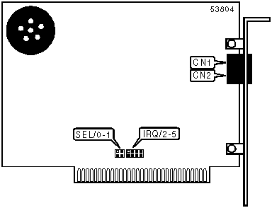
CONNECTIONS | ||||||
|
Function |
Label |
Function |
Label | |||
|
Line out/in - Unidentified |
CN1 |
Line in/out - Unidentified |
CN2 | |||
|
SERIAL PORT ADDRESS | ||
|
Setting |
SEL/0 |
SEL/1 |
|
COM1 (3F8h) |
Open |
Open |
|
í COM2 (2F8h) |
Closed |
Open |
|
COM3 (3E8h) |
Open |
Closed |
|
COM4 (2E8h) |
Closed |
Closed |
|
INTERRUPT | ||||
|
Setting |
IRQ/2 |
IRQ/3 |
IRQ/4 |
IRQ/5 |
|
2 |
Closed |
Open |
Open |
Open |
|
í 3 |
Open |
Closed |
Open |
Open |
|
4 |
Open |
Open |
Closed |
Open |
|
5 |
Open |
Open |
Open |
Closed |
|
SUPPORTED COMMAND SET |
|
Basic AT Commands |
|
AT, ‘+++’, ‘comma’, A/ |
|
A, C, D, E, F, H, L, N, O, P, Q, R, S, T, U, V, W, Y, Z |
|
&A, &B, &C, &G, &J, &K, &L, &P, &S, &T, &V, &W, &X, &Y, &Z |
|
Extended AT Commands |
|
\C, \E, \O, \Q, \T, \U, \V, \X, \Y, \Z |
|
%A, %TT |
|
S Registers |
|
S0, S1, S2, S3, S4, S5, S6, S7, S8, S9, S10, S11, S12, S18, S25, S26, |
|
S38, S46, S48, S82, S86, S90, S91, S92, S95, S99, S108, S109, S110 |
|
Special Commands |
|
"H, "N, "O,-J, )M, +MS? |
|
Note: See MHI Help File for full command documentation. |
Proprietary AT Command Set
|
AUTO-FALLBACK/FALL-FORWARD | |
|
Type: |
Configuration |
|
Format: |
AT [cmds] %Gn [cmds] |
|
Description: |
Selects auto-fallback/fall-forward |
|
Command |
Function |
|
%G0 |
Auto-fallback/fall-forward disabled |
|
í %G1 |
Auto-fallback/fall-forward enabled |
|
AUTO-RETRAIN | |
|
Type: |
Configuration |
|
Format: |
AT [cmds] %En [cmds] |
|
Description: |
Controls auto-retrain mode |
|
Command |
Function |
|
í %E0 |
Auto-retrain disabled |
|
%E1 |
Auto-retrain enabled |
|
BIT-MAPPED REGISTER S13 | |||||
|
Format: |
AT [cmds] S13=n [cmds] | ||||
|
Default: |
0 | ||||
|
Range: |
0-8 | ||||
|
Description: |
Controls DTR dialing during asynchronous mode | ||||
|
Bit |
Value |
Function | |||
|
2 - 0 |
í 000 |
Not used | |||
|
3 |
í 01 |
DTR auto-dialing In asynchronous mode disabled DTR auto-dialing In asynchronous mode enabled | |||
|
BIT-MAPPED REGISTER S14 | ||
|
Format: |
AT [cmds] S14=n [cmds] | |
|
Default: |
Unidentified | |
|
Range: |
0-174 | |
|
Unit: |
Bit-mapped | |
|
Description: |
Controls echo, result codes and display, dial mode, and answer/originate mode. | |
|
Bit |
Value |
Function |
|
0 |
í 0 |
Not used |
|
1 |
0 í 1 |
Command echo disabled Command echo enabled |
|
2 |
í 01 |
Result codes enabled Result codes disabled |
|
3 |
0 í 1 |
Display result codes in numeric format Display result codes in verbose format |
|
4 |
í 0 |
Not used |
|
5 |
í 01 |
Tone dial enabled Pulse dial enabled |
|
6 |
í 0 |
Not used |
|
7 |
0 1 |
Answer mode enabled Originate mode enabled |
|
BIT-MAPPED REGISTER S21 | ||
|
Format |
AT [cmds] S21=n [cmds] | |
|
Default: |
4 | |
|
Range: |
0-253 | |
|
Unit: |
Bit-mapped | |
|
Description: |
Selects jack type, CTS/DCD/DSR signals, low DTR action, and the long space disconnect function. | |
|
Bit |
Value |
Function |
|
0 |
í 01 |
Selects RJ-11, RJ-41S, or RJ45S jack Selects RJ-12 or RJ-13 jack |
|
1 |
í 0 |
Not used |
|
2 |
0 í 1 |
CTS forced high CTS follows RTS |
|
4, 3 |
í 0001 10 11 |
Modem does not respond to DTR Modem hangs-up if off-hook & auto-answer is disabled Modem hangs up if off-hook & auto-answer not disabled Modem switches to asynchronous command state |
|
5 |
í 01 |
DCD forced high DCD normal |
|
6 |
í 01 |
DSR forced high DSR normal |
|
7 |
í 01 |
Long space disconnect function disabled Long space disconnect function enabled |
|
BIT-MAPPED REGISTER S22 | ||
|
Format |
AT [cmds] S22=n [cmds] | |
|
Default: |
118 | |
|
Range: |
0-127 | |
|
Unit: |
Bit-mapped | |
|
Description: |
Controls speaker volume and controls, and limits results codes. | |
|
Bit |
Value |
Function |
|
1, 0 |
00 01 í 1011 |
Low level volume Low level volume Medium level volume High level volume |
|
3, 2 |
00 í 0110 11 |
Speaker off Speaker off on carrier Speaker always on Speaker on during handshake |
|
6 - 4 |
000 100 101 110 í 111 |
Basic result codes only enabled Basic and connection speed result codes enabled Basic and connection speed result codes and dialtone detection enabled All result codes except dialtone detection enabled All result codes enabled |
|
BIT-MAPPED REGISTER S23 | ||
|
Format |
AT [cmds] S23=n [cmds] | |
|
Default: |
55 | |
|
Range: |
0-189 | |
|
Unit: |
Bit-mapped | |
|
Description: |
Grants/denies remote digital loopback, controls DTE rate and parity, and sets guard tone. | |
|
Bit |
Value |
Function |
|
0 |
0 í 1 |
Remote digital loopback denied Remote digital loopback allowed |
|
3 - 1 |
000 001 010 í 011100 101 110 111 |
Sets serial port speed to 0-300bps Sets serial port speed to 600bps Sets serial port speed to 1200bps Sets serial port speed to 2400bps Sets serial port speed to 4800bps Sets serial port speed to 9600bps Sets serial port speed to 19200bps Sets serial port speed to 38400bps or higher |
|
5, 4 |
00 01 10 í 11 |
Parity even Not Used Parity odd No Parity |
|
7, 6 |
í 0001 10 |
Guard tone disabled Guard tone 550Hz enabled Guard tone 1800Hz enabled |
|
BIT-MAPPED REGISTER S27 | ||
|
Format |
AT [cmds] S27=n [cmds] | |
|
Default: |
73 | |
|
Range: |
0-11 | |
|
Unit: |
Bit-mapped | |
|
Description: |
Selects synchronous/asynchronous mode, line type, clock source, and ITU-T/Bell modes. | |
|
Bit |
Value |
Function |
|
3, 1, 0 |
000 001 010 011 100 í 101110 |
Asynchronous Direct mode Asynchronous off-line command mode and synchronous connect mode Asynchronous off-line command mode - modem auto-dials first number in directory, then synchronous connect mode. Asynchronous off-line command mode on low DTR, synchronous connect mode on high DTR. Not Used Asynchronous Reliable Mode Asynchronous Normal Mode |
|
2 |
í 01 |
Switched line (PSTN/Dial-up) Leased line |
|
5, 4 |
í 0001 10 |
Modem generates clock DTE generates clock Modem generates clock from the receive carrier signal |
|
6 |
0 í 1 |
ITU/T mode Bell mode |
|
BIT-MAPPED REGISTER S28 | ||
|
Format |
AT [cmds] S28=n [cmds] | |
|
Default: |
Unidentified | |
|
Range: |
0-31 | |
|
Unit: |
Bit-mapped | |
|
Description: |
Controls V.23 split speed, transmit/receive speed, half duplex; and pulse dialing. | |
|
Bit |
Value |
Function |
|
0 |
í 01 |
V.23 split speed operation disabled V.23 split speed operation enabled |
|
1 |
0 1 |
75bps transmit, 1200bps receive enabled 1200bps transmit, 75bps receive enabled |
|
2 |
0 1 |
1200bps transmit, 1200bps receive disabled 1200bps transmit, 1200bps receive enabled |
|
4, 3 |
í 0001 10 11 |
39ms make/61ms break at 10pps 33ms make/67ms break at 10pps 39ms make/61ms break at 20pps 33ms make/67ms break at 20pps |
|
BIT-MAPPED REGISTER S31 | |||
|
Format: |
AT [cmds] S31=n [cmds] | ||
|
Default: |
2 | ||
|
Range: |
0-10 | ||
|
Description: |
Select automode and extended result code format. | ||
|
Bit |
Value |
Function | |
|
0 |
í 0 |
Not used | |
|
1 |
0 í 1 |
Auto-mode disabled Auto-mode enabled | |
|
3, 2 |
í 0001 10 |
Enables CONNECT result codes to report DTE speed Full reporting of CONNECT result codes Enables CONNECT result codes to report DCE speed | |
|
BIT-MAPPED REGISTER S40 | ||
|
Format |
AT [cmds] S40=n [cmds] | |
|
Default: |
Unidentified | |
|
Range: |
0-239 | |
|
Unit: |
Bit-mapped | |
|
Description: |
Controls power level and break handling; selects MNP extended services, link negotiation, and block size. | |
|
Bit |
Value |
Function |
|
0 |
0 1 |
V.42 LAPM to MNP 10 connection disabled V.42 LAPM to MNP 10 connection enabled |
|
1 |
0 í 1 |
Power level adjustment disabled Power level adjustment enabled |
|
2 |
í 01 |
Link will be negotiated at highest possible speed Link will be negotiated at 1200bps |
|
5, 4, 3 |
000 001 010 011 100 í 101 |
\K0 \K1 \K2 \K3 \K4 \K5 |
|
7, 6 |
00 01 í 1011 |
MNP block size is 64 characters MNP block size is 128 characters MNP block size is 192 characters MNP block size is 256 characters |
|
BIT-MAPPED REGISTER S41 | ||
|
Format |
AT [cmds] S41=n [cmds] | |
|
Default: |
Unidentified | |
|
Range: |
0-31 | |
|
Unit: |
Bit-mapped | |
|
Description: |
Selects compression, auto-retrain, flow control, and MNP mode. | |
|
Bit |
Value |
Function |
|
1 - 0 |
00 01 10 11 |
Data compression disabled MNP5 enabled V.42bis enabled MNP5 and V.42bis enabled |
|
2 |
í 01 |
Auto-retrain disabled Auto-retrain enabled |
|
3 |
í 01 |
Flow control disabled Flow control enabled |
|
4 |
í 01 |
Stream mode for MNP Block mode for MNP |
|
BIT-MAPPED REGISTER S192 | |||||
|
Format: |
AT [cmds] S192=n [cmds] | ||||
|
Default: |
2 | ||||
|
Range: |
0-243 | ||||
|
Description: |
Controls silent Answer Snoop Mode, adaptive answer mode, V.34 rate limiting, rate renegotiating display, demo mode, and silent answer reason code | ||||
|
Bit |
Value |
Function | |||
|
0 |
í 01 |
Standard - Full CNG. A "Snoop" occurs for 3 seconds after each ring, and for 12 seconds after the last ring. Fast - CNG Tone Only. A "Snoop" occurs for 3 seconds after each ring, and for 5 seconds after the last ring. | |||
|
1 |
0
í 1 |
Attempt data carrier first (FAX fallback if failed data). In this mode, adaptive answer accept data carriers primarily and switches to FAX mode if DATA was not successful. No CNG tone required, any and all failed DATA connections are handled as valid FAX call attempts. Attempt data carrier first (FAX if CNG tone). In this mode, adaptive answer accept data carriers primarily wait until data carrier answer tone for 4 seconds to allow a possible CNG tone detect to occur; but switches to FAX mode when a CNG tone is detected. | |||
|
3, 2 |
í 00 |
Not used | |||
|
4 |
í 01 |
V34 rate limiting disabled V34 rate limiting enabled; The modem will connect using the rate from +MS, after a connection is made all data rates more than one step below the connection rate will be disabled. | |||
|
5 |
í 01 |
Rate Renegotiating Display disabled Rate Renegotiating Display enabled | |||
|
6 |
í 01 |
Demo Mode disabled Demo Mode enabled; modem displays V34 288 LP DC as if it is connected. Issue ATZ to return normal operation. | |||
|
7 |
í 01 |
Silent answer reason code disabled Silent answer reason code enabled; "CNG -- SA": Silent Answer or Silent Answer Plus code detects CNG. "CNG -- Adaptive Answer": Adaptive Answer code detects CNG. "DATA Time-out": Data mode timed out during an Adaptive Answer. | |||
|
BIT-MAPPED REGISTER S201 | |||||
|
Format: |
AT [cmds] S201=n [cmds] | ||||
|
Default: |
Unidentified | ||||
|
Range: |
0-63 | ||||
|
Description: |
Controls power level, and compromise equalizer. | ||||
|
Bit |
Value |
Function | |||
|
4 - 0 |
00000 00001 00010 ... 01010 01011 ...to... 11111 |
Initial power level -26dBm Initial power level -30dBm Initial power level -10dBm ... Initial power level -10dBm Initial power level -11dBm ...to... Initial power level -31dBm | |||
|
5 |
0 1 |
Equalizer disabled Equalizer enabled | |||
|
BIT-MAPPED REGISTER S210 | |||||
|
Format: |
AT [cmds] S210=n [cmds] | ||||
|
Default: |
Unidentified | ||||
|
Range: |
0-13 | ||||
|
Description: |
Controls Baud rate and V.34 asymmetric carrier rate. | ||||
|
Bit |
Value |
Function | |||
|
2 - 0 |
000 001 010 011 100 í 101 |
Baud rate Data rates 2400 2400 - 21800bps 2400 4800 - 24000bps 2400,2800 4800 - 24000bps 2400,2800,3000 4800 - 26400bps 2400,2800,3000,3200 4800 - 28800bps 2400,2800,3000,3200,3429 4800 - 28800bps | |||
|
3 |
0 1 |
V.34 transmit and receive carriers use the same rate V.34 transmit and receive Carriers may use different rates | |||
|
BLACKLISTED NUMBERS | |
|
Type: |
Immediate |
|
Format: |
AT [cmds] *B [cmds] |
|
Description: |
Displays a numbered chart of BLACKLISTED numbers, except permanently forbidden numbers based on country setting. "OK" is returned if no numbers are blacklisted. |
|
BREAK SEND | |
|
Type: |
Configuration |
|
Format: |
AT [cmds] \Bn [cmds] |
|
Default: |
Unidentified |
|
Range: |
1-9 |
|
Unit: |
.1 second |
|
Description: |
Sends break to modem in non-error correction state |
|
BREAK TYPE | ||||
|
Type: |
Configuration | |||
|
Format: |
AT [cmds] \Kn [cmds] | |||
|
Description: |
Configures action of break signal | |||
|
Command |
Break from DTE |
Modem receives \B |
Break received from remote modem | |
|
\K0 |
Online command mode enabled, send no break to remote modem |
Break sent to remote modem and buffers cleared |
Buffers cleared, break sent to DTE | |
|
\K1 |
Break sent to remote modem and buffers cleared |
Break sent to remote modem and buffers cleared |
Buffers cleared, break sent to DTE | |
|
\K2 |
Online command mode enabled, send no break to remote modem |
Send break to remote modem immediately |
Break sent immediately to DTE | |
|
\K3 |
Send break to remote modem immediately |
Send break to remote modem immediately |
Break sent immediately to DTE | |
|
\K4 |
Online command mode enabled, send no break to remote modem |
Send break with transmitted data |
Break sent with received data to the DTE | |
|
í \K5 |
Send break with transmitted data |
Send break with transmitted data |
Break sent with received data to the DTE | |
|
CALLER ID | |
|
Type: |
Configuration |
|
Format: |
AT [cmds] #CID=n [cmds] |
|
Description: |
Controls the Caller ID function |
|
Command |
Function |
|
#CID? |
Displays current Caller ID mode |
|
#CID=? |
Returns Caller ID modes supported |
|
#CID=0 |
Caller ID disabled |
|
#CID=1 |
Caller ID displays formatted data |
|
#CID=2 |
Caller ID displays raw hexadecimal data |
|
COMMUNICATIONS MODE | |
|
Type: |
Configuration |
|
Format: |
AT [cmds] &Mn [cmds] |
|
Description: |
Selects communications mode |
|
Note: Same function as &Q(0-3) settings. | |
|
Command |
Mode |
|
í &M0 |
Asynchronous Direct mode |
|
&M1 |
Asynchronous off-line command mode and synchronous connect mode. |
|
&M2 |
Asynchronous off-line command mode - modem auto-dials first number in directory, then synchronous connect mode. |
|
&M3 |
Asynchronous off-line command mode on low DTR, synchronous connect mode on high DTR. |
|
COMMUNICATIONS MODE | |
|
Type: |
Configuration |
|
Format: |
AT [cmds] &Qn [cmds] |
|
Description: |
Selects communications mode options |
|
Command |
Mode |
|
&Q0 |
Asynchronous Direct mode |
|
&Q1 |
Asynchronous off-line command mode and synchronous connect mode. |
|
&Q2 |
Asynchronous off-line command mode - modem auto-dials first number in directory, then synchronous connect mode. |
|
&Q3 |
Asynchronous off-line command mode on low DTR, synchronous connect mode on high DTR. |
|
&Q4 |
Not Used |
|
í &Q5 |
Asynchronous Reliable Mode |
|
&Q6 |
Asynchronous Normal Mode |
Note: Be VERY careful when issuing these commands! Once you enter &Q(1-3) and save it to memory,there are only two known ways to return to Asynchronous Mode: 1. Issue AT &Q(0,5-9) &W from a Synchronous Terminal to restore the modem to Asynchronous Mode. 2. Connect modem to an Asynchronous Terminal with the DTR signal (line 20) disabled (a "break-out" box works very nicely for this) and issue the configuration you want or AT &Q(0,5-9) &W to return the modem to Asynchronous Mode. | |
|
COMMUNICATION PROTOCOLS | ||
|
Type: |
Configuration | |
|
Format: |
AT [cmds] Bn [cmds] | |
|
Description: |
Selects the communication protocol for data calls | |
Note: The B command allows the simultaneous selection of more than one suffix, enabling multiple protocols. | ||
|
Command |
Function | |
|
B0 |
V.21 (1200bps) and V.22 (1200 bps) | |
|
B1 |
Bell 103 (300 bps) and Bell 212A (1200 bps) | |
|
COMPRESSION | |
|
Type: |
Configuration |
|
Format: |
AT [cmds] %Cn [cmds] |
|
Description: |
Selects data compression |
|
Command |
Function |
|
%C0 |
Data compression disabled |
|
%C1 |
MNP5 enabled |
|
%C2 |
V.42bis enabled |
|
%C3 |
MNP5 and V.42bis enabled |
|
CONNECT MODE | |
|
Type: |
Configuration |
|
Format: |
AT [cmds] \Nn [cmds] |
|
Description: |
Controls the type of connection the modem will operate in |
|
Command |
Function |
|
\N0 |
Normal mode enabled |
|
\N1 |
Direct mode enabled |
|
\N2 |
Reliable mode enabled |
|
í \N3 |
Auto-reliable mode enabled |
|
\N4 |
V.42 reliable mode enabled |
|
\N5 |
MNP reliable mode enabled |
|
COUNTRY CODE | ||||
|
Type: |
Configuration | |||
|
Format: |
AT [cmds] *NCn [cmds] | |||
|
Description: |
Sets the country code | |||
|
Command |
Function |
Command |
Function | |
|
*NC? |
Displays country codes and configurations currently supported |
*NC013 |
Spain | |
|
*NC000 |
United States |
*NC014 |
Sweden | |
|
*NC001 |
Austria |
*NC015 |
Switzerland | |
|
*NC002 |
Belgium |
*NC016 |
United Kingdom | |
|
*NC003 |
Denmark |
*NC017 |
Greece | |
|
*NC004 |
Finland |
*NC020 |
Canada | |
|
*NC005 |
France |
*NC021 |
Mexico | |
|
*NC006 |
Germany |
*NC022 |
United States | |
|
*NC007 |
Ireland |
*NC040 |
Australia | |
|
*NC008 |
Italy |
*NC043 |
Japan | |
|
*NC010 |
Netherlands |
*NC047 |
Singapore | |
|
*NC011 |
Norway |
*NC048 |
New Zealand | |
|
*NC012 |
Portugal |
*NC060 |
South Africa | |
|
DATA TERMINAL READY (DTR) | |||||
|
Type: |
Configuration | ||||
|
Format: |
AT [cmds] &Dn [cmds] | ||||
|
Description: |
Selects modem response to DTR | ||||
Note: The action each variant of &D causes depends on the setting of &Q | |||||
|
&Q Setting |
&D0 |
&D1 |
&D2 |
&D3 | |
|
&Q0, &Q5, &Q6 |
Command 0 |
Command 3 |
Command 1 |
Command 4 | |
|
&Q1, &Q4 |
Command 2 |
Command 3 |
Command 1 |
Command 4 | |
|
&Q2, &Q3 |
Command 1 |
Command 1 |
Command 1 |
Command 1 | |
|
Command |
Function | ||||
|
Command 0 |
Modem does not respond to DTR | ||||
|
Command 1 |
Modem hangs-up if off-hook & auto-answer is disabled | ||||
|
Command 2 |
Modem hangs up if off-hook & auto-answer not disabled | ||||
|
Command 3 |
Modem switches to asynchronous command state | ||||
|
Command 4 |
Modem performs soft reset | ||||
|
DELAYED NUMBERS | |
|
Type: |
Immediate |
|
Format: |
AT [cmds] *D [cmds] |
|
Description: |
Displays a numbered chart of DELAYED numbers and the length of delay in the format HH:MM:SS. "OK" is returned if no numbers are delayed. |
|
DIAL | ||
|
Type: |
Immediate | |
|
Format: |
AT [cmds] D<#> [cmds] | |
|
Description: |
Dials telephone number according to any modifiers included in the string | |
|
Note: Any combination of modifiers can be used to produce the desired dial functions in sequence. | ||
|
Command |
Function | |
|
- ( ) i |
These symbols and spaces are ignored | |
|
L |
Dial the last dialing string | |
|
J |
Perform MNP10 link negotiation at 1200bps (one-shot) | |
|
K |
Enable power level adjustment during MNP10 link negotiation (one-shot) | |
|
P |
Pulse dial the following digits | |
|
R |
Accepted, but no action occurs | |
|
Sn |
Use dialing string stored in register n. n=0-3 | |
|
T |
Tone dial the following digits | |
|
W |
Wait for second dialtone, Within the time set in S6 and/or S7 | |
|
* |
DTMF code for "star" | |
|
# |
DTMF code for "gate" | |
|
& |
Wait for "bong" Credit Card billing tone | |
|
@ |
Wait for quiet answer, A 5 second silence. | |
|
, |
Pause before finishing dialing string, time set in S8 | |
|
! |
Hook flash, go on-hook for 700ms, maybe changed by S29. | |
|
^ |
Turn on 1300Hz call originating pulse | |
|
; |
Return to command state | |
|
DIALING CODES | ||
|
Type: |
Configuration | |
|
Format: |
AT [cmds] *Zn [cmds] | |
|
Description: |
Sets pulse dialing. Used for countries that supports 2 pulse dialing methods. | |
|
Command |
Function | |
|
í *Z0 |
Dial code 0 | |
|
*Z1 |
Dial code 1 | |
|
DISTICTIVE RING | |||||
|
Type: |
Configuration | ||||
|
Format: |
AT [cmds] -SDR=n [cmds] | ||||
|
Default: |
0 | ||||
|
Range: |
0-7 | ||||
|
Description: |
Selects distinctive ring and result code | ||||
|
Note: -SDR? = Reports current distinctive ring used | |||||
|
Bit |
Value |
Function | |||
|
0 |
í 01 |
Single rings and report as RING 1 disabled Single rings and report as RING 1 enabled | |||
|
1 |
í 01 |
Double rings and report as RING 2 disabled Double rings and report as RING 2 enabled | |||
|
2 |
í 01 |
Triple rings and report as RING 3 disabled Triple rings and report as RING 3 enabled | |||
|
DISPLAYS CURRENT SETTINGS | |
|
Type: |
Immediate |
|
Format: |
AT [cmds] \S [cmds] |
|
Description: |
Displays Active Configuration |
|
DISPLAYS MANUFACTURER | |
|
Type: |
Immediate |
|
Format: |
AT [cmds] +GMI [cmds] |
|
Description: |
Displays manufacturer ID |
|
DISPLAYS MODEL | |
|
Type: |
Immediate |
|
Format: |
AT [cmds] +GMM [cmds] |
|
Description: |
Displays model ID |
|
DISPLAYS ROM CODE | |
|
Type: |
Immediate |
|
Format: |
AT [cmds] +GMR [cmds] |
|
Description: |
Displays ROM Code ID |
|
EQM AUTOMATIC RATE ADAPTION BIAS | |
|
Type: |
Register |
|
Format |
AT [cmds] S191=n [cmds] |
|
Default: |
129 |
|
Range: |
0-255 |
|
Unit: |
Unidentified |
|
Description: |
Controls the bias for V.32/32bis,V.FC, and V.34 operation. Linked to AT%Q, but doesn’t affect it. |
|
EQM QUALITY TIMER | |
|
Type: |
Register |
|
Format |
AT [cmds] S190=n [cmds] |
|
Default: |
60 |
|
Range: |
10-255 |
|
Unit: |
1 second |
|
Description: |
Sets the minimum time period the EQM (%Q) level must be "GOOD" before attempting to fall-forward to a higher rate. Affects AT%E2%G1 setting |
|
FACTORY DEFAULT PROFILE | ||
|
Type: |
Configuration | |
|
Format: |
AT [cmds] &F [cmds] | |
|
Description: |
Sets values in active profile to values found in the default profile | |
|
Command |
Function | |
|
&F0 |
No flow control, No error correction, No data compression | |
|
&F1 |
MAC hardware flow control, correction & compression active | |
|
&F2 |
Hardware flow control, correction & compression active | |
|
FLASH DIAL MODIFIER TIME | |
|
Type: |
Register |
|
Format |
AT [cmds] S29=n [cmds] |
|
Default: |
7 |
|
Range: |
0-255 |
|
Unit: |
.1 second |
|
Description: |
Time the modem will go on-hook upon receiving the ! dial modifier in dial string. S29=0 will disable flash hook function. |
|
FLASH ROM | |
|
Type: |
Immediate |
|
Format: |
AT [cmds] ** [cmds] |
|
Description: |
Set FLASH ROM code XMODEM upload mode |
|
FLOW CONTROL | |
|
Type: |
Configuration |
|
Format: |
AT [cmds] \Gn [cmds] |
|
Description: |
Selects modem port flow control for Normal and Direct modes |
|
Command |
Function |
|
í \G0 |
Flow control disabled |
|
\G1 |
Flow control enabled |
|
FLOW CONTROL | |
|
Type: |
Read-only Register |
|
Format |
AT [cmds] S39? [cmds] |
|
Description: |
Displays the current flow control |
|
Value |
Meaning |
|
0 |
Flow control disabled |
|
3 |
RTS/CTS flow control enabled |
|
4 |
XON/XOFF flow control enabled |
|
5 |
Transparent XON/XOFF flow control enabled |
|
6 |
Both XON/XOFF and RTS/CTS enabled |
|
FLOW CONTROL CHARACTER - XON | |
|
Type: |
Register |
|
Format: |
AT [cmds] S32=n [cmds] |
|
Default: |
17 |
|
Range: |
0-255 |
|
Unit: |
ASCII |
|
Description: |
Sets the character used to represent XON |
|
FLOW CONTROL CHARACTER - XOFF | |
|
Type: |
Register |
|
Format: |
AT [cmds] S33=n [cmds] |
|
Default: |
19 |
|
Range: |
0-255 |
|
Unit: |
ASCII |
|
Description: |
Sets the character used to represent XOFF |
|
INACTIVITY TIMER | |
|
Type: |
Register |
|
Format |
AT [cmds] S30=n [cmds] |
|
Default: |
0 |
|
Range: |
0-255 |
|
Unit: |
10 seconds |
|
Description: |
Maximum duration of DTE and DCE inactivity allowed prior to initiating hang-up process. |
Note: S30=0 disables the timer and allows indefinite inactivity. In Reliable mode any data transfer resets timer. In Normal mode only sent data resets timer. | |
|
LINE SIGNAL LEVEL | |
|
Type: |
Immediate |
|
Format |
AT [cmds] %L [cmds] |
|
Default: |
Unidentified |
|
Range: |
9-46 |
|
Unit: |
-dBm |
|
Description: |
Returns a value which indicates the received line signal level |
|
LINE SIGNAL QUALITY | |
|
Type: |
Immediate |
|
Format |
AT [cmds] %Q [cmds] |
|
Default: |
Unidentified |
|
Range: |
0-127 |
|
Unit: |
Unidentified |
|
Description: |
Returns a value which indicates line signal quality (EQM) |
|
LOCK SERIAL PORT | |
|
Type: |
Configuration |
|
Format: |
AT [cmds] \Jn [cmds] |
|
Description: |
Sets operation of serial port speed |
|
Command |
Function |
|
\J0 |
Serial speed locked |
|
\J1 |
Serial speed follows connect speed |
|
MAXIMUM BLOCK SIZE FOR TRANSMISSION | |
|
Type: |
Configuration |
|
Format: |
AT [cmds] \An [cmds] |
|
Description: |
Sets the maximum transmittable block size |
|
Command |
Function |
|
\A0 |
MNP block size is 64 characters |
|
í \A1 |
MNP block size is 128 characters |
|
\A2 |
MNP block size is 192 characters |
|
\A3 |
MNP block size is 256 characters |
|
MNP MODE | ||
|
Type: |
Configuration | |
|
Format: |
AT [cmds] -Cn [cmds] | |
|
Description: |
Controls which MNP mode is selected | |
|
Command |
Function | |
|
-C0 |
Enable MNP 10 sync mode | |
|
-C1 |
Enable MNP 10 async mode | |
|
-C2 |
Enable MNP 2 | |
|
-C3 |
Enable MNP 3 | |
|
MNP - EXTENDED SERVICES | |
|
Type: |
Configuration |
|
Format: |
AT [cmds] -Kn [cmds] |
|
Description: |
Selects MNP extended services (MNP10) |
|
Command |
Function |
|
í -K0 |
V.42 LAPM to MNP 10 connection disabled |
|
-K1 |
V.42 LAPM to MNP 10 connection enabled |
|
-K2 |
MNP 10 extended services detection enabled |
|
MNP - STREAM/BLOCK MODE | |
|
Type: |
Configuration |
|
Format: |
AT [cmds] \Ln [cmds] |
|
Description: |
Selects the transfer mode for MNP link |
|
Command |
Function |
|
í \L0 |
Stream mode for MNP enabled |
|
\L1 |
Block mode for MNP enabled |
|
MNP10 - FALLBACK | |
|
Type: |
Configuration |
|
Format: |
AT [cmds] -Qn [cmds] |
|
Description: |
Allows MNP10 to fall back to speeds slower than 4800bps |
|
Command |
Function |
|
-Q0 |
MNP10 at 4800bps only enabled |
|
í -Q1 |
MNP10 at 2400 and 1200bps enabled |
|
MNP10 - FALL-FORWARD | |
|
Type: |
Configuration |
|
Format: |
AT [cmds] -Un [cmds] |
|
Description: |
Controls forced transmit level change during MNP10 fall-forward |
|
Command |
Function |
|
-U0 |
Automatic attenuation to -10dBm |
|
-U1 |
Automatic attenuation to as low as -18dBm |
|
-U2 |
Automatic attenuation to as low as -22dBm |
|
-U3 |
Automatic attenuation to as low as -25dBm |
|
-U4 |
Forced 2400bps transmit level to -10dBm |
|
-U5 |
Forced 2400bps transmit level to -18dBm |
|
-U6 |
Forced 2400bps transmit level to -22dBm |
|
-U7 |
Forced 2400bps transmit level to -25dBm |
|
MNP10 - LINK NEGOTIATION | |
|
Type: |
Configuration |
|
Format: |
AT [cmds] *Hn [cmds] |
|
Description: |
Sets the speed at which MNP10 link negotiation will occur |
|
Command |
Function |
|
í *H0 |
Link will be negotiated at highest possible speed |
|
*H1 |
Link will be negotiated at 1200bps |
|
*H2 |
Link will be negotiated at 4800bps |
|
MNP10 - POWER LEVEL ADJUST | |
|
Type: |
Configuration |
|
Format: |
AT [cmds] )Mn [cmds] |
|
Description: |
Controls automatic transmit power level adjustment during MNP 10 link negotiation |
|
Command |
Function |
|
í )M0 |
Power level adjustment disabled |
|
)M1 |
Power level adjustment enabled |
|
MODULATION SELECTION | |
|
Type: |
Configuration |
|
Format: |
AT [cmds] +MS=x,y,z,a [cmds] |
|
Default: |
AT+MS=11,1,300,28800<cr> |
|
Description: |
Sets options for active protocol; the transfer rates specified by z (minimum) and a (maximum) must be valid for the protocol selected. |
|
Command |
Function |
|
+MS=? |
Displays supported +MS options and range |
|
x=0 |
V.21 |
|
x=1 |
V.22 |
|
x=2 |
V.22bis |
|
x=3 |
V.23 |
|
x=9 |
V.32 |
|
x =10 |
V.32bis |
|
í x=11 |
V.34 |
|
x =64 |
Bell 103 |
|
x =69 |
Bell 212A |
|
x =74 |
V.FC |
|
y =0 |
Automode disabled |
|
í y=1 |
Auto-detect highest speed enabled |
|
z, a=300 |
Set minimum or maximum transfer rate at 300bps, respectively. |
|
z, a =1200 |
Set minimum or maximum transfer rate at 1200bps, respectively. |
|
z, a =2400 |
Set minimum or maximum transfer rate at 2400bps, respectively. |
|
z, a =4800 |
Set minimum or maximum transfer rate at 4800bps, respectively. |
|
z, a =7200 |
Set minimum or maximum transfer rate at 7200bps, respectively. |
|
z, a =9600 |
Set minimum or maximum transfer rate at 9600bps, respectively. |
|
z, a =12000 |
Set minimum or maximum transfer rate at 12000bps, respectively. |
|
z, a =14400 |
Set minimum or maximum transfer rate at 14400bps, respectively. |
|
z, a =16800 |
Set minimum or maximum transfer rate at 16800bps, respectively. |
|
z, a =19200 |
Set minimum or maximum transfer rate at 19200bps, respectively. |
|
z, a =21600 |
Set minimum or maximum transfer rate at 21600bps, respectively. |
|
z, a =24000 |
Set minimum or maximum transfer rate at 24000bps, respectively. |
|
z, a =26400 |
Set minimum or maximum transfer rate at 26400bps, respectively. |
|
z, a =28800 |
Set minimum or maximum transfer rate at 28800bps, respectively. |
|
PHASE 1 BUSY | |||||
|
Type: |
Register | ||||
|
Format: |
AT [cmds] SCn=x [cmds] | ||||
|
Description: |
Sets the way the modem accepts a busy signal by FCC specifications | ||||
|
Command |
Value |
Function | |||
|
SC0=x |
42 |
Minimum BUSY ON Time | |||
|
SC1=x |
0 |
Minimum BUSY ON Time | |||
|
SC2=x |
58 |
Maximum BUSY ON Time | |||
|
SC3=x |
0 |
Maximum BUSY ON Time | |||
|
SC4=x |
42 |
Minimum BUSY OFF Time | |||
|
SC5=x |
0 |
Minimum BUSY OFF Time | |||
|
SC6=x |
58 |
Maximum BUSY OFF Time | |||
|
SC7=x |
0 |
Maximum BUSY OFF Time | |||
|
SC8=x |
4 |
Number of Cycles | |||
|
PHASE 1 RINGBACK | |||||
|
Type: |
Register | ||||
|
Format: |
AT [cmds] SCn=x [cmds] | ||||
|
Description: |
Sets the way the modem accepts a ringback signal by FCC specifications | ||||
|
Command |
Value |
Function | |||
|
SC9=x |
90 |
Minimum ON Time | |||
|
SC10=x |
0 |
Minimum ON Time | |||
|
SC11=x |
300 |
Maximum ON Time | |||
|
SC12=x |
0 |
Maximum ON Time | |||
|
SC13=x |
290 |
Minimum OFF Time | |||
|
SC14=x |
0 |
Minimum OFF Time | |||
|
SC15=x |
460 |
Maximum OFF Time | |||
|
SC16=x |
0 |
Maximum OFF Time | |||
|
SC17=x |
1 |
Number of Cycles | |||
|
PHASE 1 CONGESTION | |||||
|
Type: |
Register | ||||
|
Format: |
AT [cmds] SCn=x [cmds] | ||||
|
Description: |
Sets the way the modem accepts a congestion signal by FCC specifications | ||||
|
Command |
Value |
Function | |||
|
SC18=x |
22 |
Minimum ON Time | |||
|
SC19=x |
0 |
Minimum ON Time | |||
|
SC20=x |
28 |
Maximum ON Time | |||
|
SC21=x |
0 |
Maximum ON Time | |||
|
SC22=x |
22 |
Minimum OFF Time | |||
|
SC23=x |
0 |
Minimum OFF Time | |||
|
SC24=x |
28 |
Maximum OFF Time | |||
|
SC25=x |
0 |
Maximum OFF Time | |||
|
SC26=x |
4 |
Number of Cycles | |||
|
PHASE 1 DIALTONE 1 | |||||
|
Type: |
Register | ||||
|
Format: |
AT [cmds] SCn=x [cmds] | ||||
|
Description: |
Sets the way the modem accepts a dialtone 1 signal by FCC specifications | ||||
|
Command |
Value |
Function | |||
|
SC27=x |
0 |
Minimum ON Time | |||
|
SC28=x |
0 |
Minimum ON Time | |||
|
SC29=x |
0 |
Maximum ON Time | |||
|
SC30=x |
0 |
Maximum ON Time | |||
|
SC31=x |
0 |
Minimum OFF Time | |||
|
SC32=x |
0 |
Minimum OFF Time | |||
|
SC33=x |
0 |
Maximum OFF Time | |||
|
SC34=x |
0 |
Maximum OFF Time | |||
|
SC35=x |
1 |
Number of Cycles | |||
|
PHASE 1 DIALTONE 2 | |||||
|
Type: |
Register | ||||
|
Format: |
AT [cmds] SCn=x [cmds] | ||||
|
Description: |
Sets the way the modem accepts a dialtone 2 signal by FCC specifications | ||||
|
Command |
Value |
Function | |||
|
SC36=x |
0 |
Minimum ON Time | |||
|
SC37=x |
0 |
Minimum ON Time | |||
|
SC38=x |
0 |
Maximum ON Time | |||
|
SC39=x |
0 |
Maximum ON Time | |||
|
SC40=x |
0 |
Minimum OFF Time | |||
|
SC41=x |
0 |
Minimum OFF Time | |||
|
SC42=x |
0 |
Maximum OFF Time | |||
|
SC43=x |
0 |
Maximum OFF Time | |||
|
SC44=x |
1 |
Number of Cycles | |||
|
PHASE 2 BUSY | |||||
|
Type: |
Register | ||||
|
Format: |
AT [cmds] SCn=x [cmds] | ||||
|
Description: |
Sets the way the modem accepts a busy signal by FCC specifications | ||||
|
Command |
Value |
Function | |||
|
SC45=x |
0 |
Minimum ON Time | |||
|
SC46=x |
0 |
Minimum ON Time | |||
|
SC47=x |
0 |
Maximum ON Time | |||
|
SC48=x |
0 |
Maximum ON Time | |||
|
SC49=x |
0 |
Minimum OFF Time | |||
|
SC50=x |
0 |
Minimum OFF Time | |||
|
SC51=x |
0 |
Maximum OFF Time | |||
|
SC52=x |
0 |
Maximum OFF Time | |||
|
SC53=x |
1 |
Number of Cycles | |||
|
PHASE 2 RINGBACK | |||||
|
Type: |
Register | ||||
|
Format: |
AT [cmds] SCn=x [cmds] | ||||
|
Description: |
Sets the way the modem accepts a ringback signal by FCC specifications | ||||
|
Command |
Value |
Function | |||
|
SC54=x |
0 |
Minimum ON Time | |||
|
SC55=x |
0 |
Minimum ON Time | |||
|
SC56=x |
0 |
Maximum ON Time | |||
|
SC57=x |
0 |
Maximum ON Time | |||
|
SC58=x |
0 |
Minimum OFF Time | |||
|
SC59=x |
0 |
Minimum OFF Time | |||
|
SC60=x |
0 |
Maximum OFF Time | |||
|
SC61=x |
0 |
Maximum OFF Time | |||
|
SC62=x |
1 |
Number of Cycles | |||
|
PHASE 2 CONGESTION | |||||
|
Type: |
Register | ||||
|
Format: |
AT [cmds] SCn=x [cmds] | ||||
|
Description: |
Sets the way the modem accepts a congestion signal by FCC specifications | ||||
|
Command |
Value |
Function | |||
|
SC61=x |
0 |
Minimum ON Time | |||
|
SC62=x |
0 |
Minimum ON Time | |||
|
SC63=x |
0 |
Maximum ON Time | |||
|
SC64=x |
0 |
Maximum ON Time | |||
|
SC65=x |
0 |
Minimum OFF Time | |||
|
SC66=x |
0 |
Minimum OFF Time | |||
|
SC67=x |
0 |
Maximum OFF Time | |||
|
SC68=x |
0 |
Maximum OFF Time | |||
|
SC69=x |
1 |
Number of Cycles | |||
|
PHASE 2 DIALTONE1 | |||||
|
Type: |
Register | ||||
|
Format: |
AT [cmds] SCn=x [cmds] | ||||
|
Description: |
Sets the way the modem accepts a dialtone 1 signal by FCC specifications | ||||
|
Command |
Value |
Function | |||
|
SC72=x |
0 |
Minimum ON Time | |||
|
SC73=x |
0 |
Minimum ON Time | |||
|
SC74=x |
0 |
Maximum ON Time | |||
|
SC75=x |
0 |
Maximum ON Time | |||
|
SC76=x |
0 |
Minimum OFF Time | |||
|
SC77=x |
0 |
Minimum OFF Time | |||
|
SC78=x |
0 |
Maximum OFF Time | |||
|
SC79=x |
0 |
Maximum OFF Time | |||
|
SC80=x |
1 |
Number of Cycles | |||
|
PHASE 2 DIALTONE2 | |||||
|
Type: |
Register | ||||
|
Format: |
AT [cmds] SCn=x [cmds] | ||||
|
Description: |
Sets the way the modem accepts a dialtone 2 signal by FCC specifications | ||||
|
Command |
Value |
Function | |||
|
SC81=x |
0 |
Minimum ON Time | |||
|
SC82=x |
0 |
Minimum ON Time | |||
|
SC83=x |
0 |
Maximum ON Time | |||
|
SC84=x |
0 |
Maximum ON Time | |||
|
SC85=x |
0 |
Minimum OFF Time | |||
|
SC86=x |
0 |
Minimum OFF Time | |||
|
SC87=x |
0 |
Maximum OFF Time | |||
|
SC88=x |
0 |
Maximum OFF Time | |||
|
SC89=x |
1 |
Number of Cycles | |||
|
PNP | ||
|
Type: |
Register | |
|
Format: |
AT [cmds] S193=n [cmds] | |
|
Description: |
Controls plug and play feature | |
|
Command |
Function | |
|
S193=0 |
Serial PNP disabled, when &F1 set | |
|
S193=1 |
Serial PNP enabled, when &F0 or &F2 set | |
|
REPORT INFORMATION | ||
|
Type: |
Immediate | |
|
Format: |
AT [cmds] In [cmds] | |
|
Description: |
Displays requested information | |
|
Command |
Function | |
|
I0 |
SupraFAXModem product ID code | |
|
I1 |
ROM checksum | |
|
I2 |
Test Checksum (OK if correct, ERROR if not) | |
|
I3 |
ROM revision code, Model name, and Firmware build date | |
|
I4 |
Encrypted report of supported protocols | |
|
I5 |
Supra Copyright and Model information | |
|
I6 |
Country Code for country PSTN Signals are Configured for | |
|
I7 |
DSP Model and Version Code | |
|
I9 |
PnP COMID string | |
|
I10 |
Supported Feature Code List, Model Name, and Code Definitions | |
|
I92 |
Product Code ID Number | |
|
REPORT INFORMATION - CONNECTION | ||
|
Type: |
Immediate | |
|
Format: |
AT [cmds] %Q1 [cmds] | |
|
Description: |
Displays information on the connection | |
|
Connection |
Display | |
|
V.32/V.32bis |
EQM: (same as %Q) Receive Level: (same as %L) Transmit Level: (current TX level in dBm) | |
|
V.FC/V.34 |
Far Echo Delay: (round trip far end echo delay in ms) Far Echo Level: (signal Strength of far echo in dBm) Pre-Emphasis Filter: (filter in use to normalize the lines frequency response as per V34 DSP specs. and ITU V.34 specs.) | |
|
V.34 only |
SNR: (signal to Noise ratio measured during the line probe, in dB) Normalized Bandwidth: (The -3dB roll off points after the pre-emphasis filter is applied. This is not the same as the usable audio band-width since the signal has been heavily processed prior to this measurement. This range determines the maximum symbol rate the line will support.) Baud rate: (symbols per second on the connection) Transmit Carrier: If the symbol rate is below 3429 there are two available carrier frequencies. (A high carrier and a low carrier.) The actual frequency of the carriers varies with the symbol rate. "high" or "low" are the only items displayed. Received Carrier: same as above on received carrier | |
|
RTS/CTS | |
|
Type: |
Configuration |
|
Format: |
AT [cmds] &Rn [cmds] |
|
Description: |
Selects RTS/CTS options |
|
Command |
Function |
|
í &R0 |
In Sync mode CTS follows RTS In Async mode CTS forced high |
|
&R1 |
In Sync mode CTS forced high In Async mode RTS/CTS forced high |
|
SC-REGISTERS | |
|
Type: |
Register |
|
Format: |
AT [cmds] SCn=x [cmds] |
|
Description: |
Each register "pair" holds the value for each setting. To set a value, divide the setting by 256. The integer goes in the second register, while the remained goes in the first. (A setting of 516 would convert to 2 Remainder 4, and could be set by sending ATSC0=4SC1=2 to the modem.) Settings are in 1/100ths of a second. Setting SC0=22 & SC4=22 allows FAST BUSY to also be detected as BUSY. |
|
SELECT CALL PROGRESS RESULT CODES | |
|
Type: |
Configuration |
|
Format: |
AT [cmds] Xn [cmds] |
|
Description: |
Enables selection of tone detection and associated result code format options |
|
Command |
Function |
|
X0 |
Basic result codes only enabled |
|
X1 |
Basic and connection speed result codes enabled |
|
X2 |
Basic and connection speed result codes and dialtone detection enabled |
|
X3 |
All result codes except dialtone detection enabled |
|
í X4 |
All result codes enabled |
|
SLEEP TIMER | |
|
Type: |
Register |
|
Format |
AT [cmds] S24=n [cmds] |
|
Default: |
0 |
|
Range: |
0-255 |
|
Unit: |
1 second |
|
Description: |
Maximum duration of DTE and DCE inactivity allowed prior to initiating low-power sleep mode. |
|
STATUS-REGISTER | ||
|
Type: |
Configuration | |
|
Format: |
AT [cmds] (see below) [cmds] | |
|
Description: |
Gives options to read or write to a specified register | |
|
Command |
Function | |
|
=n |
Write value n to the last S register viewed | |
|
? |
Displays current setting for the last S register accessed | |
|
Sr? |
Reports value in S register r | |
|
Sr.b? |
Reports value in S register r (not just bit b) | |
|
SCr? |
Reports value is SC register r | |
|
Sr=n |
Write value n into S register r | |
|
Sr.b=n |
Write value (0 or 1) to bit b of S register r | |
|
SCr=n |
Write value n into SC register r | |
|
TEST MODES | ||
|
Type: |
Register | |
|
Format: |
AT [cmds] S16=n [cmds] | |
|
Default: |
0 | |
|
Range: |
0-125 | |
|
Unit: |
Bit-mapped | |
|
Description: |
Controls loopback tests, analog, digital, remote digital, and self tests. | |
|
Bit |
Value |
Function |
|
0 |
í 01 |
Local analog loopback not in progress Local analog loopback in progress |
|
1 |
í 0 |
Not used |
|
2 |
í 01 |
Local digital loopback not in progress Local digital loopback in progress |
|
3 |
í 01 |
Modem not in remote digital loopback Remote digital loopback in progress |
|
4 |
í 01 |
Remote digital loopback not requested Remote digital loopback requested |
|
5 |
í 01 |
Remote digital loopback w/ self-test not in progress Remote digital loopback w/ self-test in progress |
|
6 |
í 01 |
Local analog loopback w/ self-test not in progress Local analog loopback w/ self-test in progress |
|
TRANSMISSION LEVEL - CELLULAR | |
|
Type: |
Configuration |
|
Format: |
AT [cmds] @Mn [cmds] |
|
Default: |
0 |
|
Range: |
0-31 |
|
Unit: |
Unidentified |
|
Description: |
Sets the signal level for transmission while in cellular mode (MNP10) |
|
V.23 MODE | ||
|
Type: |
Configuration | |
|
Format: |
AT [cmds] %Fn [cmds] | |
|
Description: |
Selects V.23 split-speed | |
|
Command |
Function | |
|
%F1 |
75bps transmit, 1200bps receive (split-speed) | |
|
%F2 |
1200bps transmit, 75bps receive (split-speed) | |
|
V.23 - SPLIT-SPEED | |
|
Type: |
Configuration |
|
Format: |
AT [cmds] \Wn [cmds] |
|
Description: |
Controls V.23 split-speed mode |
|
Command |
Function |
|
í \W0 |
V.23 split-speed mode disabled |
|
\W1 |
V.23 split-speed mode enabled |
|
V.32 - COMPROMISE EQUALIZER | |
|
Type: |
Configuration |
|
Format: |
AT [cmds] :En [cmds] |
|
Description: |
Controls V.32 compromise equalizer |
|
Command |
Function |
|
:E0 |
Equalizer disabled |
|
:E1 |
Equalizer enabled |