PURE DATA LTD.
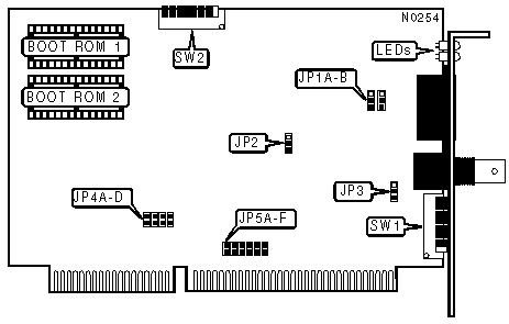
PDI515
|
NIC Type |
ARCnet |
|
Transfer Rate |
2.5Mbps |
|
Data Bus |
16-bit ISA |
|
Topology |
Star Linear Bus |
|
Wiring Type |
RG-62A/U 93ohm coaxial Shielded/Unshielded twisted pair |
|
Boot ROM |
Available |
|
NODE ADDRESS | ||||||||
|
Node |
SW1/1 |
SW1/2 |
SW1/3 |
SW1/4 |
SW1/5 |
SW1/6 |
SW1/7 |
SW1/8 |
|
0 |
- |
- |
- |
- |
- |
- |
- |
- |
|
1 |
On |
On |
On |
On |
On |
On |
On |
Off |
|
2 |
On |
On |
On |
On |
On |
On |
Off |
On |
|
3 |
On |
On |
On |
On |
On |
On |
Off |
Off |
|
4 |
On |
On |
On |
On |
On |
Off |
On |
On |
|
251 |
Off |
Off |
Off |
Off |
Off |
On |
Off |
Off |
|
252 |
Off |
Off |
Off |
Off |
Off |
Off |
On |
On |
|
253 |
Off |
Off |
Off |
Off |
Off |
Off |
On |
Off |
|
254 |
Off |
Off |
Off |
Off |
Off |
Off |
Off |
On |
|
255 |
Off |
Off |
Off |
Off |
Off |
Off |
Off |
Off |
|
Note:Node address 0 is used for messaging between nodes and must not be used. A total of 255 node address settings are available. The switches are a binary representation of the decimal node addresses. Switch 8 is the Least Significant Bit and switch 1 is the Most Significant Bit. The switches have the following decimal values: switch 8=1, 7=2, 6=4, 5=8, 4=16, 3=32, 2=64, 1=128. Turn off the switches and add the values of the off switches to obtain the correct node address. (On=0, off=1) | ||||||||
|
MEMORY ADDRESS MODE | ||
|
Mode |
SW2/1 | |
| » |
16-bit memory addressing mode |
On |
|
8-bit memory addressing mode |
Off | |
|
Note:Two boot ROMs must be installed for 16-bit memory addressing mode. | ||
|
COMPATABILITY MODE | ||
|
Mode |
SW2/2 | |
| » |
Normal |
Off |
|
Special |
On | |
|
BASE MEMORY ADDRESS | |||
|
Address |
SW2/3 |
SW2/4 |
SW2/5 |
|
C0000 - C3FFFh |
On |
On |
On |
|
C4000 - C7FFFh |
On |
On |
Off |
|
CC000 - CFFFFh |
On |
Off |
On |
|
D0000 - D3FFFh |
On |
Off |
Off |
|
D4000 - D7FFFh |
Off |
On |
On |
|
D8000 - DBFFFh |
Off |
On |
Off |
|
DC000 - DFFFFh |
Off |
Off |
On |
|
I/O BASE ADDRESS | |||
|
Address |
SW2/6 |
SW2/7 |
SW2/8 |
|
260h |
On |
On |
On |
|
290h |
On |
On |
Off |
|
2E0h |
On |
Off |
On |
|
2F0h |
On |
Off |
Off |
|
300h |
Off |
On |
On |
|
350h |
Off |
On |
Off |
|
380h |
Off |
Off |
On |
|
3E0h |
Off |
Off |
Off |
|
CABLE TYPE | ||
|
Type |
JP1A & JP1B | |
| » |
Shielded/Unshielded twisted pair |
Pins 1 & 2 Closed |
|
RG-62A/U 93ohm coaxial |
Pins 2 & 3 Closed | |
|
MEMORY MODE | ||
|
Mode |
JP2 | |
| » |
Shared Memory mode enabled |
Pins 2 & 3 Closed |
|
Mapped I/O mode enabled |
Pins 1 & 2 Closed | |
|
Note:When Mapped I/O mode is enabled, SW2/1 (Memory address mode) must be in 8-bit mode (off). | ||
|
TOPOLOGY CONFIGURATION | ||
|
Topology |
JP3 | |
| » |
Star Topology |
Pins 1 & 2 Closed |
|
Bus Topology |
Pins 2 & 3 Closed | |
|
INTERRUPT REQUEST | ||||||||||
|
IRQ |
JP4A |
JP4B |
JP4C |
JP4D |
JP5A |
JP5B |
JP5C |
JP5D |
JP5E |
JP5F |
|
2 |
Open |
Open |
Open |
Open |
Closed |
Open |
Open |
Open |
Open |
Open |
|
3 |
Open |
Open |
Open |
Open |
Open |
Closed |
Open |
Open |
Open |
Open |
|
4 |
Open |
Open |
Open |
Open |
Open |
Open |
Closed |
Open |
Open |
Open |
|
5 |
Open |
Open |
Open |
Open |
Open |
Open |
Open |
Closed |
Open |
Open |
|
6 |
Open |
Open |
Open |
Open |
Open |
Open |
Open |
Open |
Closed |
Open |
|
7 |
Open |
Open |
Open |
Open |
Open |
Open |
Open |
Open |
Open |
Closed |
|
10 |
Closed |
Open |
Open |
Open |
Open |
Open |
Open |
Open |
Open |
Open |
|
11 |
Open |
Closed |
Open |
Open |
Open |
Open |
Open |
Open |
Open |
Open |
|
12 |
Open |
Open |
Closed |
Open |
Open |
Open |
Open |
Open |
Open |
Open |
|
15 |
Open |
Open |
Open |
Closed |
Open |
Open |
Open |
Open |
Open |
Open |
|
DIAGNOSTIC LED(S) | ||
|
Color |
Status |
Condition |
|
Red |
Flasing on power-up |
Card is performing a self-test |
|
Red |
On |
I/O bus activity detected |
|
Red |
Off |
No I/O bus activity detected |
|
Green |
On |
Data is being transmitted or receiving |
|
Green |
Blinking |
Card is not connected to network or network not active |