D-LINK SYSTEMS, INC.
DX-100
|
NIC Type |
Arcnet |
|
Chipset |
D-Link |
|
Network Transfer Rate |
2.5Mbps |
|
Data Bus |
8-bit ISA |
|
Topology |
Linear Bus |
|
Wire Type |
Unshielded twisted pair |
|
Boot ROM |
Available |
|
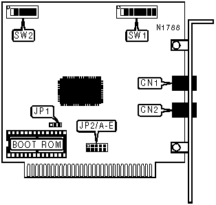
CONNECTIONS | |||
|
Function |
Label |
Function |
Label |
|
Unshielded twisted pair connector |
CN1 |
Unshielded twisted pair connector |
CN2 |
|
USER CONFIGURABLE SETTINGS | |||
|
Setting |
Label |
Position | |
| » |
Boot ROM disabled |
JP1 |
Pins 2 & 3 closed |
|
Boot ROM enabled |
JP1 |
Pins 1 & 2 closed | |
|
INTERRUPT | ||||||
|
Setting |
JP2/A |
JP2/B |
JP2/C |
JP2/D |
JP2/E | |
| » |
IRQ2 |
Closed |
Open |
Open |
Open |
Open |
|
IRQ3 |
Open |
Closed |
Open |
Open |
Open | |
|
IRQ4 |
Open |
Open |
Closed |
Open |
Open | |
|
IRQ5 |
Open |
Open |
Open |
Closed |
Open | |
|
IRQ7 |
Open |
Open |
Open |
Open |
Closed | |
|
BASE I/O ADDRESS | ||||
|
Setting |
SW2/1 |
SW2/2 |
SW2/3 | |
|
260h |
On |
On |
On | |
|
290h |
Off |
On |
On | |
| » |
2E0h |
On |
Off |
On |
|
300h |
On |
On |
Off | |
|
350h |
Off |
On |
Off | |
|
380h |
On |
Off |
Off | |
|
3E0h |
Off |
Off |
Off | |
|
SHARED RAM AND BOOT ROM ADDRESS | |||||
|
Shared RAM |
Boot ROM |
SW2/4 |
SW2/5 |
SW2/6 | |
|
C0000h |
C2000h |
On |
On |
On | |
|
C4000h |
C6000h |
Off |
On |
On | |
|
C8000h |
CA000h |
On |
Off |
On | |
|
CC000h |
CE000h |
Off |
Off |
On | |
| » |
D0000h |
D2000h |
On |
On |
Off |
|
D4000h |
D6000h |
Off |
On |
Off | |
|
D8000h |
D8000h |
On |
Off |
Off | |
|
DC000h |
DE000h |
Off |
Off |
Off | |
|
NODE ADDRESS | ||||||||
|
Setting |
SW1/1 |
SW1/2 |
SW1/3 |
SW1/4 |
SW1/5 |
SW1/6 |
SW1/7 |
SW1/8 |
|
1 |
Off |
On |
On |
On |
On |
On |
On |
On |
|
2 |
On |
Off |
On |
On |
On |
On |
On |
On |
|
3 |
Off |
Off |
On |
On |
On |
On |
On |
On |
|
4 |
On |
On |
Off |
On |
On |
On |
On |
On |
|
5 |
Off |
On |
Off |
On |
On |
On |
On |
On |
|
250 |
On |
Off |
On |
Off |
Off |
Off |
Off |
Off |
|
251 |
Off |
Off |
On |
Off |
Off |
Off |
Off |
Off |
|
252 |
On |
On |
Off |
Off |
Off |
Off |
Off |
Off |
|
253 |
Off |
On |
Off |
Off |
Off |
Off |
Off |
Off |
|
254 |
On |
Off |
Off |
Off |
Off |
Off |
Off |
Off |
|
Note: A total of 254 node address settings are available. The switches are a binary representation of the decimal node addresses. SW1/8 is the Most Significant Bit and switch SW1/1 is the Least Significant Bit. The switches have the following decimal values: SW1/8=128, SW1/7=64, SW1/6=32, SW1/5=16, SW1/4=8, SW1/3=4, SW1/2=2, SW1/1=1. Turn off the switches and add the values of the switches that are off to obtain the correct node ID. (Off=1, On=0)Node addresses 0 and 255 are reserved and should not be used. | ||||||||