DATAPOINT CORPORATION
ARCNET PLUS
|
NIC Type |
ARCnet |
|
Transfer Rate |
2.5Mbps/20Mbps |
|
Data Bus |
16-bit ISA |
|
Topology |
Star Linear bus |
|
Wiring Type |
RG-62A/U 93ohm coaxial |
|
Boot ROM |
Available |
|
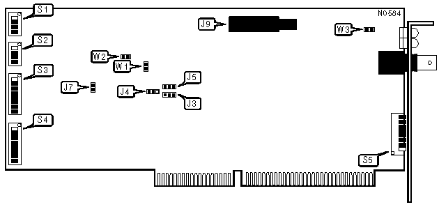
CONNECTIONS | |
|
Purpose |
Location |
|
Coaxial connector for internal PC hub |
J9 |
|
BOOT ROM CONFIGURATION | ||
|
Setting |
S1/1 | |
| » |
Disabled |
Off |
|
Enabled |
On | |
|
BLOCK DECODE SIZE | ||
|
Block Size |
S1/2 | |
| » |
16KB memory block decode |
On |
|
128KB memory block decode |
Off | |
|
Note:A 16-bit VGA adapter typically decodes base memory in 128KB blocks. If you are installing the NIC in a system with such a card, you may need to set the NIC block decode size to 128KB. If you set the block decode size to 128KB then all other 16-bit cards in the system must utilize 128KB decode. NIC must be in 16-bit mode for this switch to be functional. | ||
|
ARCNET MODE CONFIGURATION | |
|
Mode |
S1/3 |
|
Normal ARCnet |
On |
|
Enhanced ARCnetPlus mode |
Off |
|
DATA BUS SIZE | ||
|
Size |
S1/4 | |
|
8-bit |
Off | |
| » |
16-bit |
On |
|
INTERRUPT REQUEST | |||||
|
IRQ |
S2/1 |
S2/2 |
S2/3 |
S2/4 | |
| » |
2/9 |
On |
Off |
On |
On |
|
3 |
Off |
Off |
On |
On | |
|
4 |
On |
On |
Off |
On | |
|
5 |
Off |
On |
Off |
On | |
|
7 |
Off |
Off |
Off |
On | |
|
10 |
On |
Off |
On |
Off | |
|
11 |
Off |
Off |
On |
Off | |
|
14 |
On |
Off |
Off |
Off | |
|
15 |
Off |
Off |
Off |
Off | |
|
I/O BASE ADDRESS | |||||||||
|
Address |
S3/1 |
S3/2 |
S3/3 |
S3/4 |
S3/5 |
S3/6 |
S3/7 |
S3/8 | |
|
260h |
On |
Off |
Off |
On |
On |
Off |
On |
On | |
|
290h |
Off |
On |
On |
Off |
On |
Off |
On |
On | |
|
2C0h |
On |
On |
Off |
Off |
On |
Off |
On |
On | |
|
2D0h |
Off |
On |
Off |
Off |
On |
Off |
On |
On | |
| » |
2E0h |
On |
Off |
Off |
Off |
On |
Off |
On |
On |
|
2F0h |
Off |
Off |
Off |
Off |
On |
Off |
On |
On | |
|
300h |
On |
On |
On |
On |
Off |
Off |
On |
On | |
|
310h |
Off |
On |
On |
On |
Off |
Off |
On |
On | |
|
320h |
On |
Off |
On |
On |
Off |
Off |
On |
On | |
|
350h |
Off |
On |
Off |
On |
Off |
Off |
On |
On | |
|
380h |
On |
On |
On |
Off |
Off |
Off |
On |
On | |
|
3E0h |
On |
Off |
Off |
Off |
Off |
Off |
On |
On | |
|
BASE MEMORY ADDRESS | |||||||
|
Base |
S4/3 |
S4/4 |
S4/5 |
S4/6 |
S4/7 |
S4/8 | |
|
C0000h |
On |
On |
On |
On |
Off |
Off | |
|
C4000h |
Off |
On |
On |
On |
Off |
Off | |
|
C8000h |
On |
Off |
On |
On |
Off |
Off | |
|
CC000h |
Off |
Off |
On |
On |
Off |
Off | |
| » |
D0000h |
On |
On |
Off |
On |
Off |
Off |
|
D4000h |
Off |
On |
Off |
On |
Off |
Off | |
|
D8000h |
On |
Off |
Off |
On |
Off |
Off | |
|
DC000h |
Off |
Off |
Off |
On |
Off |
Off | |
|
Note:S4/1 and S4/2 are not used. | |||||||
|
NODE ADDRESS | ||||||||
|
Node |
S5/1 |
S5/2 |
S5/3 |
S5/4 |
S5/5 |
S5/6 |
S5/7 |
S5/8 |
|
0 |
- |
- |
- |
- |
- |
- |
- |
- |
|
1 |
On |
On |
On |
On |
On |
On |
On |
Off |
|
2 |
On |
On |
On |
On |
On |
On |
Off |
On |
|
3 |
On |
On |
On |
On |
On |
On |
Off |
Off |
|
4 |
On |
On |
On |
On |
On |
Off |
On |
On |
|
251 |
Off |
Off |
Off |
Off |
Off |
On |
Off |
Off |
|
252 |
Off |
Off |
Off |
Off |
Off |
Off |
On |
On |
|
253 |
Off |
Off |
Off |
Off |
Off |
Off |
On |
Off |
|
254 |
Off |
Off |
Off |
Off |
Off |
Off |
Off |
On |
|
255 |
Off |
Off |
Off |
Off |
Off |
Off |
Off |
Off |
|
Note:Node address 0 is used for messaging between nodes and must not be used. A total of 255 node address settings are available. The switches are a binary representation of the decimal node addresses. Switch 8 is the Least Significant Bit and switch 1 is the Most Significant Bit. The switches have the following decimal values: switch 1=128, 2=64, 3=32, 4=16, 5=8, 6=4, 7=2, 8=1. Turn Off the switches and add the values of the Off switches to obtain the correct node address. (On=0, Off=1) | ||||||||
|
RESPONSE AND RECONFIGURATION TIMEOUTS | ||||
|
Timeout |
J3 |
J5 |
J4 | |
| » |
840ms |
Open |
Open |
Open |
|
1.68 sec |
Open |
Open |
Closed | |
|
3.36 sec |
Open |
Closed |
Open | |
|
6.72 sec |
Open |
Closed |
Closed | |
|
13.44 sec |
Closed |
Open |
Open | |
|
26.88 sec |
Closed |
Open |
Closed | |
|
53.76 sec |
Closed |
Closed |
Open | |
|
1.7887 min |
Closed |
Closed |
Closed | |
|
Note:All NICs on the network segment must have this option set the same. | ||||
|
BUFFER RAM SIZE | |||
|
Size |
Chip |
W1 | |
|
8KB |
8K x 8 |
Open | |
| » |
32KB |
32K x 8 |
Closed |
|
MICRO-CODE ROM SIZE | ||
|
Size |
W2 | |
| » |
4KB |
Open |
|
8KB |
Closed | |
|
LOGIC/CHASSIS GROUND | ||
|
Setting |
W3 | |
| » |
RFI grounding enabled |
Closed |
|
RFI grounding disabled |
Open | |
|
FACTORY CONFIGURED SETTINGS | |||
|
Function |
Jumper |
Setting | |
| » |
Factory test mode disabled |
JP7 |
Closed |

|
DIAGNOSTIC LED | |||
|
LED |
Color |
Status |
Condition |
|
LED1 |
Amber |
On |
PC is currently accessing adapter card |
|
LED1 |
Amber |
Flashing |
Initial power-on self test |
|
LED1 |
Amber |
Pulsating |
Software driver initialization |
|
LED1 |
Amber |
Off |
PC to NIC communication idle |
|
LED2 |
Green |
On |
Transmission in progress |
|
LED2 |
Green |
Flashing |
Connection to network in progress |
|
LED2 |
Green |
Off |
No network connection, or card malfunction |
|
Note:Location of LED1 is unknown. | |||