TMC RESEARCH CORPORATION
CAT54IT, CAP54IT (VERSIONS 1.0 AND 1.00)
|
Processor |
Pentium |
|
Processor Speed |
75/90/100/120/133/150/166/180/200MHz |
|
Chip Set |
Intel |
|
Video Chip Set |
None |
|
Maximum Onboard Memory |
128MB (EDO supported) |
|
Maximum Video Memory |
None |
|
Cache |
256/512KB |
|
BIOS |
Unidentified |
|
Dimensions |
Unidentified |
|
I/O Options |
Floppy drive interface, green PC connector, IDE interfaces (2), parallel port, PS/2 mouse interface, serial ports (2), cache slot, IR connector |
|
NPU Options |
None |
|
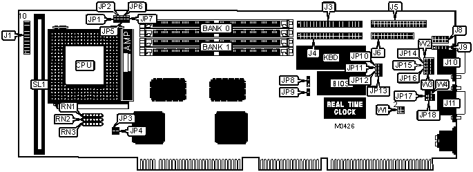
CONNECTIONS | |||
|
Purpose |
Location |
Purpose |
Location |
|
Speaker |
J1 pins 1 - 4 |
Floppy drive interface |
J5 |
|
Green PC connector |
J1 pins 6 & 16 |
Parallel port |
J6 |
|
Turbo LED |
J1 pins 8 & 18 |
PS/2 mouse interface |
J8 |
|
Reset switch |
J1 pins 9 & 19 |
IR connector |
J9 |
|
IDE interface LED |
J1 pins 10 & 20 |
Serial port 1 |
J10 |
|
Power LED & keylock |
J1 pins 11 - 15 |
Serial port 2 |
J11 |
|
IDE interface 1 |
J3 |
Cache slot |
SL1 |
|
IDE interface 2 |
J4 | ||
|
Note: IR connector is only available on boards with the SMC 37C665Ir/669 chip installed. | |||
|
USER CONFIGURABLE SETTINGS | |||
|
Function |
Label |
Position | |
|
» |
AT bus clock speed select PCI clock 1/4 |
JP7 |
Closed |
|
AT bus clock speed select PCI clock 1/3 |
JP7 |
Open | |
|
» |
Flash BIOS voltage select 5v (SST) |
JP8 |
Pins 2 & 3 closed |
|
Flash BIOS voltage select 12v (Intel) |
JP8 |
Pins 1 & 2 closed | |
|
» |
Watch dog timer time out select 1 second |
JP9 |
Open |
|
Watch dog timer time out select 500ms |
JP9 |
Closed | |
|
» |
Flash BIOS write protect disabled (see note below) |
JP10 |
Open |
|
Flash BIOS write protect enabled (see note below) |
JP10 |
Closed | |
|
» |
Password normal operation (see note below) |
JP11 |
Open |
|
Password clear (see note below) |
JP11 |
Closed | |
|
» |
CMOS memory normal operation |
JP12 |
Open |
|
CMOS memory clear |
JP12 |
Closed | |
|
» |
PS/2 mouse disabled |
JP13 |
Open |
|
PS/2 mouse enabled |
JP13 |
Closed | |
|
» |
System reset when watch dog timer times out |
JP16 |
Pins 1 & 2 closed |
|
Activate NMI to CPU when watch dog timer times out |
JP16 |
Pins 2 & 3 closed | |
|
Watch dog timer disabled |
JP16 |
Open | |
|
Jumper information unavailable |
RN1 |
Unidentified | |
|
Jumper information unavailable |
RN2 |
Unidentified | |
|
Jumper information unavailable |
RN3 |
Unidentified | |
|
Jumper information unavailable |
W1 |
Unidentified | |
|
Jumper information unavailable |
W2 |
Unidentified | |
|
Jumper information unavailable |
W3 |
Unidentified | |
|
Jumper information unavailable |
W4 |
Unidentified | |
|
Note: Jumpers JP10 and JP11 are not present on CAP54IT version 1.0. | |||
|
DRAM CONFIGURATION | ||
|
Size |
Bank 0 |
Bank 1 |
|
8MB |
(2) 1M x 36 |
None |
|
8MB |
None |
(2) 1M x 36 |
|
16MB |
(2) 2M x 36 |
None |
|
16MB |
None |
(2) 2M x 36 |
|
16MB |
(2) 1M x 36 |
(2) 1M x 36 |
|
24MB |
(2) 1M x 36 |
(2) 2M x 36 |
|
24MB |
(2) 2M x 36 |
(2) 1M x 36 |
|
32MB |
(2) 4M x 36 |
None |
|
32MB |
None |
(2) 4M x 36 |
|
32MB |
(2) 2M x 36 |
(2) 2M x 36 |
|
40MB |
(2) 1M x 36 |
(2) 4M x 36 |
|
40MB |
(2) 4M x 36 |
(2) 1M x 36 |
|
48MB |
(2) 2M x 36 |
(2) 4M x 36 |
|
48MB |
(2) 4M x 36 |
(2) 2M x 36 |
|
64MB |
(2) 8M x 36 |
None |
|
DRAM CONFIGURATION (CON’T) | ||
|
Size |
Bank 0 |
Bank 1 |
|
64MB |
None |
(2) 8M x 36 |
|
64MB |
(2) 4M x 36 |
(2) 4M x 36 |
|
72MB |
(2) 1M x 36 |
(2) 8M x 36 |
|
72MB |
(2) 8M x 36 |
(2) 1M x 36 |
|
80MB |
(2) 2M x 36 |
(2) 8M x 36 |
|
80MB |
(2) 8M x 36 |
(2) 2M x 36 |
|
96MB |
(2) 4M x 36 |
(2) 8M x 36 |
|
96MB |
(2) 8M x 36 |
(2) 4M x 36 |
|
128MB |
(2) 8M x 36 |
(2) 8M x 36 |
|
Note: Board accepts EDO memory. Board also accepts x 32 SIMMs. | ||
|
CACHE CONFIGURATION | |
|
Size |
SL1 |
|
256KB |
256KB module installed |
|
512KB |
512KB module installed |
|
CPU SPEED SELECTION (PENTIUM) | ||||||
|
CPU speed |
Clock speed |
Multiplier |
JP1 |
JP2 |
JP5 |
JP6 |
|
75MHz |
50MHz |
1.5x |
Closed |
Closed |
Open |
Open |
|
90MHz |
60MHz |
1.5x |
Open |
Closed |
Open |
Open |
|
100MHz |
66MHz |
1.5x |
Closed |
Open |
Open |
Open |
|
120MHz |
60MHz |
2x |
Open |
Closed |
Closed |
Open |
|
133MHz |
66MHz |
2x |
Closed |
Open |
Closed |
Open |
|
150MHz |
60MHz |
2.5x |
Open |
Closed |
Closed |
Closed |
|
166MHz |
66MHz |
2.5x |
Closed |
Open |
Closed |
Closed |
|
180MHz |
60MHz |
3x |
Open |
Closed |
Open |
Closed |
|
200MHz |
66MHz |
3x |
Closed |
Open |
Open |
Closed |
|
CPU VOLTAGE SELECTION | |||
|
Voltage |
JP3 |
JP4 | |
|
2.5v (P55) |
Open |
Open | |
| » |
3.3v (P54) |
Closed |
Closed |
|
DMA CHANNEL SELECTION | ||
|
Channel |
JP17 |
JP18 |
|
1 |
Pins 1 & 2 closed |
Pins 1 & 2 closed |
|
3 |
Pins 2 & 3 closed |
Pins 2 & 3 closed |
|
SERIAL PORT 2 SELECTION | ||
|
Setting |
JP14 |
JP15 |
|
Used as COM2 |
Pins 1 & 2 closed |
Pins 1 & 2 closed |
|
Used as IR connector |
Pins 2 & 3 closed |
Pins 2 & 3 closed |
|
Note: Above settings are only available if the SMC 37C665Ir/669 chip is installed. | ||