GESPAC
GESSBS-40
|
Device Type |
Mainboard |
|
Processor |
68040 |
|
Processor Speed |
33MHz |
|
Chip Set |
Unidentified |
|
Video Chip Set |
None |
|
Maximum Onboard Memory |
None |
|
Maximum Video Memory |
None |
|
Cache |
Unidentified |
|
BIOS |
Unidentified |
|
Dimensions |
160mm x 100mm |
|
I/O Options |
Serial ports (2), G-96 bus interface, I/O interface connector, XSB local expansion submodule buses (2) |
|
NPU Options |
None |
|
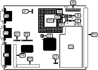
CONNECTIONS | |||
|
Purpose |
Location |
Purpose |
Location |
|
Multi processor module |
C1 |
Serial port 1 |
P4 |
|
G-96 bus interface |
P1 |
XSB local expansion submodule bus |
P5 |
|
I/O interface connector |
P2 |
XSB local expansion submodule bus |
P6 |
|
Serial port 2 |
P3 |
Reset/abort switch |
P7 |
|
USER CONFIGURABLE SETTINGS | |||
|
Function |
Label |
Position | |
|
EPROM size select 64K x 16 or 128K x 16 |
J1 |
Pins 1 & 2 closed | |
|
EPROM size select 256K x 16 |
J1 |
Pins 2 & 3 closed | |
|
RTC battery disabled |
J2 |
Pins 1 & 4 closed | |
|
RTC battery enabled |
J2 |
Pins 2 & 3 closed | |
|
Cache enabled |
J4/pins 1 & 4 |
Open | |
|
Cache disabled |
J4/pins 1 & 4 |
Closed | |
|
PNMU enabled |
J4/pins 2 & 3 |
Open | |
|
PNMU disabled |
J4/pins 2 & 3 |
Closed | |
|
Base address select for dual ported RAM < 32MB |
J5 |
Pins 1 & 2 closed | |
|
Base address select for dual ported RAM > 32MB |
J5 |
Pins 2 & 3 closed | |
|
SYSCLK speed select CPU = SYSCLK |
J6 |
Pins 1 & 2 closed | |
|
SYSCLK speed select CPU = SYSCLK/2 |
J6 |
Pins 2 & 3 closed | |
|
External cache access enabled |
J7 |
Open | |
|
External cache access disabled |
J7 |
Closed | |
|
Enable & SYSCLK and BGRT driven |
J8 |
Pins 2 & 3 closed | |
|
Enable & SYSCLK and BGRT not driven |
J8 |
Open | |
|
» |
Factory configured - do not alter |
P8 |
Unidentified |
|
DUAL PORTED RAM-BASE ADDRESS SELECTION | |
|
Address |
J9 |
|
A21 |
Pins 11 & 12 closed |
|
A22 |
Pins 10 & 13 closed |
|
A23 |
Pins 9 & 14 closed |
|
A24 |
Pins 8 & 15 closed |
|
A25 |
Pins 7 & 16 closed |
|
A26 |
Pins 6 & 17 closed |
|
A27 |
Pins 5 & 18 closed |
|
A28 |
Pins 4 & 19 closed |
|
A29 |
Pins 3 & 20 closed |
|
A30 |
Pins 2 & 21 closed |
|
A31 |
Pins 1 & 22 closed |
|
STANDBY BATTERY POWER SELECTION | |
|
Setting |
J3 |
|
From P1-29b (+Vbatt bus line) |
Pin 1 |
|
To MAX696 power supply supervisor chip |
Pin 2 |
|
From local battery |
Pin 3 |
|
Note: Location of LEDs is unidentified. | |
|
DIAGNOSTIC LED(S) | |||
|
LED |
Color |
Status |
Condition |
|
LED1 |
Red |
On |
Processor is in supervisor mode |
|
LED2 |
Orange |
On |
Processor attempting to access and external module & it has not yet the owner of the G-6432 bus module |
|
LED3 |
Yellow |
On |
GESSBS-40 is retrying an aborted cycle |
|
LED4 |
Green |
On |
Processor is halted or during a reset operation |