AXIOM TECHNOLOGY, INC.
AX8025H
|
Processor |
80386SX/CX486SLC |
|
Processor Speed |
20/25/33/40MHz |
|
Chip Set |
ALI |
|
Max. Onboard DRAM |
16MB |
|
Cache |
None |
|
BIOS |
AMI |
|
Dimensions |
169mm x 122mm |
|
I/O Options |
Floppy drive interface, IDE interface, parallel port, serial ports (2) |
|
NPU Options |
80387SX/CX387 |
|
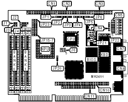
CONNECTIONS | |||
|
Purpose |
Location |
Purpose |
Location |
|
Floppy drive interface |
CN1 |
PC/104 bus connector |
CN11 |
|
IDE interface |
CN2 |
Reset switch |
J1 |
|
Parallel port |
CN3 |
Power LED & keylock |
J2 |
|
Auxiliary keyboard connector |
CN4 |
IDE interface LED |
J3 |
|
Serial port 1 |
CN7 |
Speaker |
J4 |
|
Serial port 2 |
CN8 |
External battery |
J5 |
|
PC/104 bus connector |
CN10 | ||
|
Note: The location of jumper J5 is unidentified. | |||
|
USER CONFIGURABLE SETTINGS | |||
|
Function |
Jumper |
Position | |
|
» |
Parallel port IRQ select IRQ7 |
CN5 |
pins 13 & 14 closed |
|
Parallel port IRQ select IRQ5 |
CN5 |
pins 15 & 16 closed | |
|
» |
Activate NMI to reset CPU when watch dog times out |
JP1 |
pins 1 & 2 closed |
|
Reset system when watch dog times out |
JP1 |
pins 2 & 3 closed | |
|
Watch dog disabled |
JP1 |
Open | |
|
» |
External battery type select DS1287/1187 |
JP2 |
pins 1 & 2 closed |
|
External battery type select MC146818 |
JP2 |
pins 2 & 3 closed | |
|
» |
Parity check enabled |
JP3 |
pins 1 & 2 closed |
|
Parity check disabled |
JP3 |
pins 2 & 3 closed | |
|
» |
Watch dog timer normal |
JP4 |
pins 2 & 3 closed |
|
Watch dog timer reset |
JP4 |
pins 1 & 2 closed | |
|
» |
IDE interface pin 34 used |
JP5 |
pins 2 & 3 closed |
|
IDE interface pin 34 not used |
JP5 |
pins 1 & 2 closed | |
|
» |
Monitor type select monochrome |
JP6 |
pins 1 & 2 closed |
|
Monitor type select color |
JP6 |
pins 2 & 3 closed | |
|
» |
IDE interface enabled |
JP7 |
pins 2 & 3 closed |
|
IDE interface disabled |
JP7 |
pins 1 & 2 closed | |
|
» |
Floppy drive interface enabled |
JP8 |
pins 2 & 3 closed |
|
Floppy drive interface disabled |
JP8 |
pins 1 & 2 closed | |
|
» |
NPU synchronous with CPU |
JP15 |
pins 2 & 3 closed |
|
NPU asynchronous with CPU |
JP15 |
pins 1 & 2 closed | |
|
» |
Time out period select 1 second |
JP21 |
pins 1 & 2 closed |
|
Time out period select 10 seconds |
JP21 |
pins 2 & 3 closed | |
|
» |
Parallel port unidirectional (printer) |
JP23 |
pins 1 & 2 closed |
|
Parallel port bidirectional |
JP23 |
pins 2 & 3 closed | |
|
DRAM CONFIGURATION | ||
|
Size |
Bank 0 |
Bank 1 |
|
1MB |
(2) 256K x 9 |
(2) 256K x 9 |
|
2MB |
(2) 1M x 9 |
NONE |
|
4MB |
(2) 1M x 9 |
(2) 1M x 9 |
|
8MB |
(2) 4M x 9 |
NONE |
|
16MB |
(2) 4M x 9 |
(2) 4M x 9 |
|
CPU TYPE CONFIGURATION | |
|
Type |
J6 |
|
80386SX |
Open |
|
CX486SLC |
pins 1 & 2, 3 & 4, 5 & 6 closed |
|
CPU SPEED CONFIGURATION | ||
|
Speed |
JP20 |
JP22 |
|
20MHz |
pins 1 & 2 closed |
pins 2 & 3 closed |
|
25MHz |
pins 2 & 3 closed |
pins 1 & 2 closed |
|
33MHz |
pins 2 & 3 closed |
pins 2 & 3 closed |
|
40MHz |
pins 1 & 2 closed |
pins 1 & 2 closed |
|
PARALLEL PORT CONFIGURATION | ||
|
Setting |
JP13 |
JP14 |
|
278 |
pins 2 & 3 closed |
pins 2 & 3 closed |
|
378 |
pins 1 & 2 closed |
pins 1 & 2 closed |
|
3BC |
pins 1 & 2 closed |
pins 2 & 3 closed |
|
Disabled |
pins 2 & 3 closed |
pins 1 & 2 closed |
|
SERIAL PORT 1 CONFIGURATION | ||
|
Setting |
JP9 |
JP10 |
|
2E8 |
pins 2 & 3 closed |
pins 1 & 2 closed |
|
3E8 |
pins 1 & 2 closed |
pins 1 & 2 closed |
|
3F8 |
pins 2 & 3 closed |
pins 2 & 3 closed |
|
Disabled |
pins 1 & 2 closed |
pins 2 & 3 closed |
|
SERIAL PORT 2 CONFIGURATION | ||
|
Setting |
JP11 |
JP12 |
|
2E8 |
pins 1 & 2 closed |
pins 1 & 2 closed |
|
2F8 |
pins 2 & 3 closed |
pins 2 & 3 closed |
|
3E8 |
pins 2 & 3 closed |
pins 1 & 2 closed |
|
Disabled |
pins 1 & 2 closed |
pins 2 & 3 closed |
|
SERIAL PORT 1 INTERRUPT CONFIGURATION | |
|
IRQ |
CN5 |
|
IRQ3 |
pins 3 & 4 closed |
|
IRQ4 |
pins 1 & 2 closed |
|
IRQ5 |
pins 5 & 6 closed |
|
SERIAL PORT 2 INTERRUPT CONFIGURATION | |
|
IRQ |
CN5 |
|
IRQ3 |
pins 7 & 8 closed |
|
IRQ4 |
pins 9 & 10 closed |
|
IRQ5 |
pins 11 & 12 closed |