QUATECH, INC.
QS-200M/300M
|
Card Type |
Serial controller |
|
Chipset/Controller |
16450/16550 UART |
|
I/O Options |
Serial ports (4) |
|
Maximum DRAM |
N/A |
|
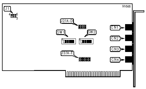
CONNECTIONS | |||
|
Purpose |
Location |
Purpose |
Location |
|
Serial port 1 - RJ-11 |
CN1 |
Serial port 3 - RJ-11 |
CN3 |
|
Serial port 2 - RJ-11 |
CN2 |
Serial port 4 - RJ-11 |
CN4 |
|
INPUT CLOCK CONFIGURATION | ||
|
MHz |
J1 | |
| » |
1.8432MHz |
Pins 1 & 4, 2 & 3, 5 & 6 closed |
|
3.6864MHz |
Pins 2 & 3, 4 & 5 closed | |
|
9.216MHz |
Pins 1 & 2, 5 & 6 closed | |
|
18.432MHz |
Pins 2 & 5 closed | |
|
DUPLEX SELECTION | |||||
|
Setting |
J2/A |
J2/B |
J2/C |
J2/D | |
| » |
Port 1 full duplex mode |
Open |
N/A |
N/A |
N/A |
|
Port 1 half duplex mode |
Closed |
N/A |
N/A |
N/A | |
| » |
Port 2 full duplex mode |
N/A |
Open |
N/A |
N/A |
|
Port 2 half duplex mode |
N/A |
Closed |
N/A |
N/A | |
| » |
Port 3 full duplex mode |
N/A |
N/A |
Open |
N/A |
|
Port 3 half duplex mode |
N/A |
N/A |
Closed |
N/A | |
| » |
Port 4 full duplex mode |
N/A |
N/A |
N/A |
Open |
|
Port 4 half duplex mode |
N/A |
N/A |
N/A |
Closed | |
|
INTERRUPT SELECT | ||||||
|
IRQ |
J3/A |
J3/B |
J3/C |
J3/D |
J3/E |
J3/F |
|
IRQ2 |
Closed |
Open |
Open |
Open |
Open |
Open |
|
IRQ3 |
Open |
Closed |
Open |
Open |
Open |
Open |
|
IRQ4 |
Open |
Open |
Closed |
Open |
Open |
Open |
|
IRQ5 |
Open |
Open |
Open |
Closed |
Open |
Open |
|
IRQ6 |
Open |
Open |
Open |
Open |
Closed |
Open |
|
IRQ7 |
Open |
Open |
Open |
Open |
Open |
Closed |
|
Note: All ports share the same IRQ. | ||||||
|
I/O ADDRESS CONFIGURATION | ||||
|
Base Address |
SW1 |
SW2 | ||
| » |
300h |
1, 2, 3, 4, 5 & 6 On |
3, 4 & 5 On | |
|
6A0h |
1, 2, 3, 4 & 5 On |
2 & 4 On | ||
|
5220h |
1, 3, 5 & 6 On |
2, 3 & 4 On | ||
|
Note (1): The address range for the QS-200M/300M is from 0 to FFFFh. The switches are a binary representation of the addresses. When a switch is off, the corresponding bit is set to 1 and has the following decimal value: SW1/1=8, SW1/2=4, SW1/3=2, SW1/4=1, SW1/5=8, SW1/6=4, SW2/1=2, SW2/2=1, SW2/3=8, SW2/4=4, SW2/5=2. The QS-200M/300M requires 32 consecutive address locations for all four serial ports. Note (2): The base address selected above is for Port 1. To obtain the addresses for the other ports, add to the Port 1 address the following numbers: Port 2 address = Port 1 address + 8 Port 3 address = Port 1 address + 16 Port 4 address = Port 1 address + 24 | ||||
|
INTERRUPT STATUS REGISTER | |
|
Setting |
SW2/6 |
|
Interrupt status register enabled |
On |
|
Interrupt status register disabled |
Off |