QUATECH, INC.
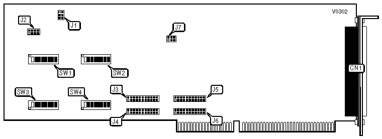
DSDP-100
|
Card Type |
Multi I/O card |
|
Chipset/Controller |
Unidentified UART |
|
I/O Options |
Parallel ports (2), serial ports (2) |
|
Maximum DRAM |
N/A |
|
CONNECTIONS | |
|
Purpose |
Location |
|
DB-62 connector |
CN1 |
|
Note:The 62-pin connector attaches to an adapter for 4 DB25 connectors (2 serial, 2 parallel). | |
|
SERIAL/PARALLEL PORT ENABLE | |
|
Port |
J2 |
|
Serial 1 |
Pins 3 & 7 closed |
|
Serial 2 |
Pins 4 & 8 closed |
|
Parallel 1 |
Pins 1 & 5 closed |
|
Parallel 2 |
Pins 2 & 6 closed |
|
Note:To disable ports, leave corresponding Pins open. | |
|
PRIMARY SERIAL PORT CONFIGURATION | ||||||||
|
Address |
SW2/1 |
SW2/2 |
SW2/3 |
SW2/4 |
SW2/5 |
SW2/6 |
SW2/7 | |
| » |
03F8h |
Off |
Off |
Off |
Off |
Off |
Off |
Off |
|
02F8h |
Off |
On |
Off |
Off |
Off |
Off |
Off | |
|
03E8h |
Off |
Off |
Off |
Off |
Off |
On |
Off | |
|
02E8h |
Off |
On |
Off |
Off |
Off |
On |
Off | |
|
SECONDARY SERIAL PORT CONFIGURATION | ||||||||
|
Address |
SW4/1 |
SW4/2 |
SW4/3 |
SW4/4 |
SW4/5 |
SW4/6 |
SW4/7 | |
| » |
02F8h |
Off |
On |
Off |
Off |
Off |
Off |
Off |
|
03F8h |
Off |
Off |
Off |
Off |
Off |
Off |
Off | |
|
03E8h |
Off |
Off |
Off |
Off |
Off |
On |
Off | |
|
02E8h |
Off |
On |
Off |
Off |
Off |
On |
Off | |
|
PRIMARY PARALLEL PORT CONFIGURATION | |||||||||
|
Address |
SW1/1 |
SW1/2 |
SW1/3 |
SW1/4 |
SW1/5 |
SW1/6 |
SW1/7 |
SW1/8 | |
| » |
0378h |
Off |
Off |
On |
Off |
Off |
Off |
Off |
On |
|
03BCh |
Off |
Off |
Off |
On |
Off |
Off |
Off |
Off | |
|
0278h |
Off |
On |
On |
Off |
Off |
Off |
Off |
On | |
|
SECONDARY PARALLEL PORT CONFIGURATION | |||||||||
|
Address |
SW3/1 |
SW3/2 |
SW3/3 |
SW3/4 |
SW3/5 |
SW3/6 |
SW3/7 |
SW3/8 | |
| » |
0278h |
Off |
On |
On |
Off |
Off |
Off |
Off |
On |
|
03BCh |
Off |
Off |
Off |
On |
Off |
Off |
Off |
Off | |
|
0378h |
Off |
Off |
On |
Off |
Off |
Off |
Off |
On | |
|
SERIAL PORT INTERRUPT SELECT | ||
|
IRQ |
J4 (Port 1) |
J6 (Port 2) |
|
IRQ2 |
Pins 1 & 12 closed |
Pins 1 & 12 closed |
|
IRQ3 |
Pins 2 & 13 closed |
Pins 2 & 13 closed |
|
IRQ4 |
Pins 3 & 14 closed |
Pins 3 & 14 closed |
|
IRQ5 |
Pins 4 & 15 closed |
Pins 4 & 15 closed |
|
IRQ6 |
Pins 5 & 16 closed |
Pins 5 & 16 closed |
|
IRQ7 |
Pins 6 & 17 closed |
Pins 6 & 17 closed |
|
IRQ10 |
Pins 7 & 18 closed |
Pins 7 & 18 closed |
|
IRQ11 |
Pins 8 & 19 closed |
Pins 8 & 19 closed |
|
IRQ12 |
Pins 9 & 20 closed |
Pins 9 & 20 closed |
|
IRQ14 |
Pins 10 & 21 closed |
Pins 10 & 21 closed |
|
IRQ15 |
Pins 11 & 22 closed |
Pins 11 & 22 closed |
|
Note:Serial port 1 has a factory default of IRQ4 and Serial port 2 has a default setting of IRQ3. | ||
|
PARALLEL PORT INTERRUPT SELECT | ||
|
IRQ |
J3 (Port 1) |
J5 (Port 2) |
|
IRQ2 |
Pins 1 & 12 closed |
Pins 1 & 12 closed |
|
IRQ3 |
Pins 2 & 13 closed |
Pins 2 & 13 closed |
|
IRQ4 |
Pins 3 & 14 closed |
Pins 3 & 14 closed |
|
IRQ5 |
Pins 4 & 15 closed |
Pins 4 & 15 closed |
|
IRQ6 |
Pins 5 & 16 closed |
Pins 5 & 16 closed |
|
IRQ7 |
Pins 6 & 17 closed |
Pins 6 & 17 closed |
|
IRQ10 |
Pins 7 & 18 closed |
Pins 7 & 18 closed |
|
IRQ11 |
Pins 8 & 19 closed |
Pins 8 & 19 closed |
|
IRQ12 |
Pins 9 & 20 closed |
Pins 9 & 20 closed |
|
IRQ14 |
Pins 10 & 21 closed |
Pins 10 & 21 closed |
|
IRQ15 |
Pins 11 & 22 closed |
Pins 11 & 22 closed |
|
Note:Parallel port 1 has a factory default of IRQ7 and Parallel port 2 has a default setting of IRQ5. | ||
|
CLOCK INPUT CONFIGURATION | |
|
Divide by |
J1 |
|
1 |
Pins 2 & 5 closed |
|
2 |
Pins 1 & 2, 5 & 6 closed |
|
5 |
Pins 2 & 3, 4 & 5 closed |
|
10 |
Pins 1 & 2, 4 & 5, 3 & 6 closed |
|
PARALLEL PORT BI-DIRECTIONAL SELECT | ||
|
Port 1 (J3) |
Port 2 (J5) |
J7 |
|
Standard |
Standard |
Pins 2 & 3, 5 & 6 closed |
|
Standard |
Bi-directional |
Pins 1 & 2, 5 & 6 closed |
|
Bi-directional |
Standard |
Pins 2 & 3, 4 & 5 closed |
|
Bi-directional |
Bi-directional |
Pins 1 & 2, 4 & 5 closed |
|
FACTORY CONFIGURED SETTINGS | |
|
Switch |
Setting |
|
SW2/8 |
N/A |
|
SW4/8 |
N/A |
|
Note:These switch positions are unused, and can be set to either on or Off. | |